Please consider the risks involved with constructing an antenna before proceeding with any project. The author shall not be liable for any loss or damage whatsoever (including human or computer error, negligent or otherwise, or incidental or consequential loss or damage) arising out of, or in connection with any use or reliance on these instructions.
This blogger is going through an addictive phase of building simple FM antennas. These DIY (Do It Yourself) antenna projects are not scary to contemplate, at all!

DIY driller bear © 2013 Stu_WP
Each project must meet the following criteria:
- the antenna must be fun to build;
- the antenna must be simple & cost effective to build &
- the antenna must offer objective measurable performance.
The first ‘victim’ is the loop! The construction consists of four quick and easy steps, detailed below.
What is a Loop antenna?
Loop antennas have been used since 1886 as receiving antennas. The loop is often ‘heard from’ but rarely seen!
MW loopstick antenna © 2008 Explain that stuff.com
An AM or MW receiver such as a Walkman, transistor radio or multi-band shortwave receiver often incorporates a loop stick (Ferrite Rod antenna) inside the receiver. This compact & inexpensive antenna is a multi-turn loop antenna wound onto a ferrite core.
The loop in today’s article is entirely different from the well-known loop stick designed for AM stations. For example, the FM loop design is by necessity, much larger in size & only one turn of wire is used in the construction. The FM loop has ‘a lot going for it’, as it features overwhelmingly positive attributes.
Characteristics of the FM Loop antenna
| ADVANTAGE |
DISADVANTAGE |
| Potential gain of up to 2 decibels compared to a half wavelength dipole. |
For maximum efficiency, the antenna may be very large for FM. |
| Exhibits the same radiation pattern as a dipole. |
Potential mismatch loss. It may be difficult to match loop to 75-76 ohm coaxial feed line as typical loop impedance is higher than a single dipole (70 ohms). |
| Suitable for indoor installations. The loop is less affected by movement of the human body than other antennas. It is easily moved between rooms without potentially scratching the walls in the process, unlike a yagi antenna. |
Full wavelength loops may not fit inside small sedans, reducing portability. |
| Variety of configurations are possible. Choose from multiple shapes! |
|
| Variety of orientations are possible. (Please refer to the suggestions on offer by Karl, KA1FSB in the links below). |
|
| Circumference may be shortened to ¾ of a wavelength for confined spaces. It may be mounted on window as stealth antenna. |
|
| Easy to build & inexpensive to build. (Please see below for four FM loop projects). |
|
| Does NOT require a ground plane. By contrast, a vertical telescopic or whip FM antenna requires a large vehicle body! That antenna also tends to exhibit a loss, NOT a gain. (Please refer to the simulations of Holl_ands). |
|
| Offers potential on a balcony as a stealth antenna. The loop may be covered with plastic or beach towel. (Please refer to the suggestions on offer by Simone IW5EDI & Mike Thompson in the links below). |
|
Build an FM loop
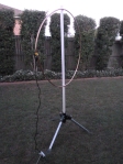
Completed FM loop on the lawn © 2014 FM DXing
Step 1. Perform software calculations (5 minutes)
Karl, KA1FSB offers an on-line calculator. The calculator suggests that for a 102.1 MHz loop, a 3 metre (9.84 ft) circumference is required. This loop exhibits a typical impedance of 102 ohms. The dipole equivalent is 1.4 metres (4.6 ft) long.
Step 2. Buy/beg/steal/borrow the materials (10 minutes)
A flexible copper coil with a length of 3 metres (9.84 ft) was purchased for $20 at a retail hardware store that sells plumbing supplies. The outer diameter is 12.7 mm (1/2 inch). It has been suggested that tubing diameter is not critical for this application.

Coiled copper tubing © 2007 neufcent9
Alternative material options: If bending can be performed, other materials such as aluminium may be used. (Steel may not be the optimal choice of antenna material; this higher resistance material exhibits a conductivity as low as 16-17% compared to copper at 92%).
Alternatively, copper or aluminium tape may be used. Copper particle conductivity paint such as CuPro-Cote may be used. Wire may be used.

Coiled roll of copper tubing © 2009 Apalca
Optional step: If cutting copper tubing to a specific length is necessary, a cutter may be purchased for about $18 or less. Please ensure the cutter is compatible with the diameter and wall thickness of the copper tubing.
Coaxial cable can be purchased for 70 cents per metre or about $5 for a two metre cable with pre-fitted F-connectors. RG59 or higher grade cable is recommended.
Step 3. Construct the antenna (20 minutes)
Inside or outside (a grassy surface is recommended) bend the copper tubing slowly by hand to form a circle. Forming the circle should take no longer than 15 minutes. Forming a perfect circle is unnecessary!
The completed circular loop is placed onto a non-conductive mast. For this construction, a $2 PVC pipe was used as the mast. The loop was fastened to the mast using plastic cable ties. Two ties are used to secure the top of the antenna to the pole; one tie for the base of the loop.
Step 4. Feedline connection (10 minutes)
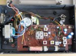
The final mandatory step is to solder a short length of coaxial cable to the ends of the loop and connect to a masthead amplifier. (The use of an amplifier with this or any other antenna is optional).

Coaxial cable inputs to loop © 2014 FM DXing
Soldering the coaxial cable to the ends of the copper tubing requires care to maintain durability. RG59 or thinner specifications of coaxial cable may be the easiest to manage without ‘weighing down’ the loop.

Feedline input to FM loop antenna with ferrite choke © 2014 FM DXing
Alternatively, aluminium or copper tape may be used as an alternative to fasten the cable to the copper. Large alligator clips are another option.
For this antenna construction, a RG59 coaxial cable with pre-fitted F-connectors was purchased. One end of the cable was cut off & stripped away to reveal the inner conductor & shield. The inner conductor is soldered to one ”leg’ of the loop antenna; the shield of the cable to the other ‘leg’.
The other end (F-connector) was connected to the masthead amplifier. Weatherproofing the connection may be necessary if the antenna will be used on a permanent basis outside.
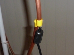
Feedline input to FM loop antenna with ferrite choke © 2014 FM DXing
Add-ons: Optional steps that may aid in optimizing the connection can be found in the Impedance Matching section, below.
The possibilities are limitless!
To receive long distance FM reception on the dual band Sangean WR-2 RDS receiver, enthusiast 1963DX constructed a quad FM loop antenna. That loop was optimized for about 109 MHz using copper wire on a wooden frame. Watch the video. Engineer Mike Thompson offers another version. About a decade ago, colleague John Faulkner G1VVP compiled a quarter wavelength version of the FM loop for the Skywaves club website. That design is made using coaxial cable. The original graphics have been mirrored at the Most Useful Information Ever.

Completed FM loop on the lawn © 2014 FM DXing
Initial testing
The FM loop is a directional antenna which exhibits gain. Performance is simple yet effective.
When placed inside the house during winter, the antenna will enable reception of the following permanent signals:
- 80 kW stations to 230 km / 143 mi;
- 10 kW stations to 221 km / 137 mi &
- 200 watt translators to 104 km / 65 mi.
Ideally for optimal performance, the antenna would obviously be placed outside. Metal objects inside for example, may cause interactions or obstructions. Outside, this antenna yields:
- 100 kW stations to 328 km / 204 mi &
- 3 kW stations to 286 km / 178 mi.
In the field, the FM loop antenna has performed extremely well. To date, the most distant evening spring-time tropospheric scatter reception occurred out to 578 km / 359 mi on an apartment balcony. Detailed field performance and photography may be found at the continually-updated Have Loop, Will Travel entry.
When the antenna is connected to a sensitive car radio or component tuner, the FM loop typically outperforms a Silabs’-based portable FM receiver with the supplied telescoping antenna. Much like a dipole, the FM loop antenna also offers good performance if connected to a portable receiver.
To be fair, crude testing under flat conditions may only offer support to assertions made about potential antenna performance! Objective measurements tend to be more reliable. These characteristics are discussed in the final section, below.
Gain
The quad loop exhibits a maximum of 1.14 decibels gain relative to a dipole (in other words, a 3.27 dBi gain) according to W8JI.
The 2005 edition of the ARRL handbook (reliant on NEC based antenna modelling data) specifies the maximum gain of a full wavelength loop to be 1.35 decibels relative to a dipole (these units are known as dBd).
For modelling comparisons between circular & square VHF loops of different dimensions, please refer to Holl_ands simulations.
What about the performance for this specific loop project? Well, modelling using MMANA-GAL Basic software suggested that maximum gain within the FM band for this loop may be as high as 1.44 dBd. Optimal SWR occurred above 105 MHz.
Comparisons to other domestic antennas
The FM loop may be ideal for long distance FM enthusiasts or listeners with a single fixed external antenna, such as a wideband television antenna.

Completed FM loop on the lawn © 2014 FM DXing
A contemporary rooftop-mounted log yagi television antenna (for US channels 6-12 & UHF) will typically exhibit a maximum gain of 1 dBd for reception at the top of the FM band & a loss for stations below 95 MHz. The loop is likely to outperform such an antenna, even on a small mast 1.7 m (5.6 ft) above ground.
The smallest & most inexpensive rooftop FM yagi antenna (3-el FM yagi) will typically exhibit a maximum gain of between 4-5 dBd. For those yagi owners, a secondary antenna such as a loop may be useful where neighbouring electrical interference is affecting the rooftop antenna, the rooftop antenna is fixed in one direction (resulting in only weak signals audible ‘off-the-side’ of the antenna) or for testing purposes in conjunction with the main antenna.
These figures are provided in good faith, based on calculations performed in antenna modelling software & antenna manufacturer data.
Polarization
As the feedline input is entering at the side, this FM loop antenna is vertically polarized. This is one of several configurations to consider.
Impedance matching
Holl_Ands modelled 82-86 MHz & high VHF band circular loops. The modelling suggests impedance varied enormously with frequency.
Various sources suggest that full wavelength loops may exhibit a typical impedance of roughly 102 – 115 ohms. In chapter four of his book, electrical engineer Walton C. Gibson suggests a circular loop exhibits an impedance of 140 ohms at resonance. This impedance is about half that of the folded dipole.

Completed FM loop on the lawn © 2014 FM DXing
Use of this antenna with standard 75 ohm feedline may cause a potential impedance mismatch. Mismatch loss may arise, where signal is reflected back to the antenna.
It could be argued that the impedance mismatch between (say) 140 ohms and 75 ohms has a negligible effect on ultimate received signal strength. Therefore, inserting a 1:1 current balun ‘home brewed’ from coaxial cable or ferrite suppression chokes represent two optional steps to consider. (Please refer to Brian’s website below). After these chokes have been inserted, a masthead amplifier may help compensate for potential mismatch loss.
Dimensions
The single dipole equivalent to this loop (with the same element diameter) is roughly 1.4 metres long, if measured tip to tip. A folded dipole requires slightly longer dimensions, typically 2%. Typically, the larger the tubing diameter, the greater is the potential bandwidth of an antenna. Element thickness is an important characteristic.
1/2 inch (12.7 mm) copper annealed coil was used to construct this loop antenna simply because the outlay was $10 cheaper than the same length of 3/4 inch (19.05 mm) coil! There were at least eight copper tubing diameters readily available to buy.
The following diameters of copper tubing are frequently used to construct circular loop antennas on the six metre, FM & high VHF broadcast bands:
- 3/8 inch (13.06 mm);
- 1/2 inch (12.7 mm) tubing or
- 1/4 inch (6.35 mm).
A final word: Mounting
As pictured, a satellite tripod is used to secure this FM loop antenna. These are priced between $50 – $70. A more inexpensive garden sprinkler tripod ($30) also works. Alternatively, mounting the FM loop inside on a large window may also be feasible. The weight of the copper tubing (dependent on the chosen thickness) will need to be secured to the window, as to ensure the antenna does not fall over!
Reference books
Antenna Basics by Christof Rohner et. al.
Antenna Design for Mobile Devices by Zhijun Zhang
Method of Moments in Electromagnetics by Walton C. Gibson
Radio Antenna Engineering by Edmund A. Laport
Reference websites
Antenna-Theory.com
Brian, K6STI
Frits, PAØFRI
Simone, IW5EDI
‘Yukon John’, KL7JR
Antenna software
John, VK5DJ
MMANA-GAL
Lecture notes & Powerpoint slides
A practical approach to HF-VHF antennas, plus antenna myths & mysteries by Terry Graves, K7FE
Computer antenna modelling simplified by Larry J. LeBlanc, KE5KJD
Loop Antenna characteristics by Pat Donohoe PhD
This entry was last updated during December 2014.


