Simple FM antennas: Introducing the Half Wave Folded Dipole

Cost:  From $ 45-75

Length: Approximately 137 cm (54″)

The Half Wave Folded Dipole comprises two elements of typically Aluminum Alloy construction. The Folded Dipole forms the active (or driven) element in a Yagi-Udi array.

Folded dipole for DAB+ bands © 2013 Digitek

Folded dipole for DAB+ bands © 2013 Digitek

How is it used?

This directional antenna is typically mounted ‘broadside’ to the desired transmitter. Experimenters may choose to add additional dipole elements or incorporate reflectors and directors.

How do I buy one?

If looking to purchase one, there are several options:

  • Remove this element from an inexpensive FM yagi. Before purchasing a yagi to ‘harvest’, please check with the retailer or manufacturer to ensure that the element can be removed; on some retail FM antennas (including the Matchmaster & Hills three element FM yagis) the folded dipole can NOT be physically detached.
  • Rescue Electronics Surplus of Connecticut custom manufactures a ceiling-mounted folded dipole. This antenna is ideal for bedrooms; cost is from $99 with worldwide shipping possible.
  • D-lenp of China manufacturers a two element FM yagi with detachable folded dipole. Cost is $25 plus shipping. Five element varieties are also available.

How do I make one?

At the end of this article there are links to Do It Yourself (DIY) antennas that enthusiasts or radio amateurs have constructed with copper tubing for FM broadcast, digital television & even 850 MHz wireless internet reception!

A folded dipole for FM may be constructed with 19 mm (0.75″) square tube aluminium extrusions or even 6, 8 or 10 mm round tube extrusions.  The choice of round tubing is recommended. Although one metre (3.3 ft) long extrusions (at several of these diameters) are widely advertised for a few dollars each from a major hardware retailer, it is usually necessary to make a custom cut of the appropriate length.

To determine the required lengths for each of the three sections of the folded dipole, please consult an on-line dipole antenna calculator or a step-by-step guide to FM yagi construction. During October*, a step-by-step DIY project will be published on this blog as part of this series on simple FM antenna building. Readers can easily and inexpensively make their own folded dipole for FM reception from copper tubing.

A potentially easier solution than the use of aluminium or copper tubing is to construct a folded dipole (or a standard single dipole) from copper or aluminium foil tape attached to a round tube PVC pipe. And better still; the total cost is far less than a round of drinks with a few lads at The Local.

Is it suitable for field trips?

Absolutely! (Most antennas are, of course but the lighter and smaller to carry the better!)

Half Wave Folded Dipole & suppression choke in sedan © 2013 FM DXing at WordPress

Half Wave Folded Dipole & suppression choke in sedan © 2013 FM DXing

How does it perform in the field?

Whenever this writer ventures into the mountains, this antenna is employed since it outperforms the factory monopole in the car. Whilst this antenna design has long been studied using computer modelling by researchers, empirical observations in the field are (hopefully) a bit more colourful for readers!

Redcliffe foreshore © 2014 Andrew Sutherland

Redcliffe foreshore © 2014 Andrew Sutherland

One of the most rewarding mobile reception achieved with this antenna (above) was rare tropospheric ducting from Nouvelle Caledonie during September of 2013, whilst parked on an unobstructed peninsula (left). Granted, even with a 19 decibel masthead signal amplifier employed in this scenario, these signals were extremely weak! Nonetheless, the bottom line is that the folded dipole antenna offers an enormous potential for any receiving application.  (If reading about mobile mountain DX fun previously published on this blog, please remember that the half wave folded dipole antenna was employed on these ‘day trips’ without exception).

Harry's Hut © 2006 Rae Allen

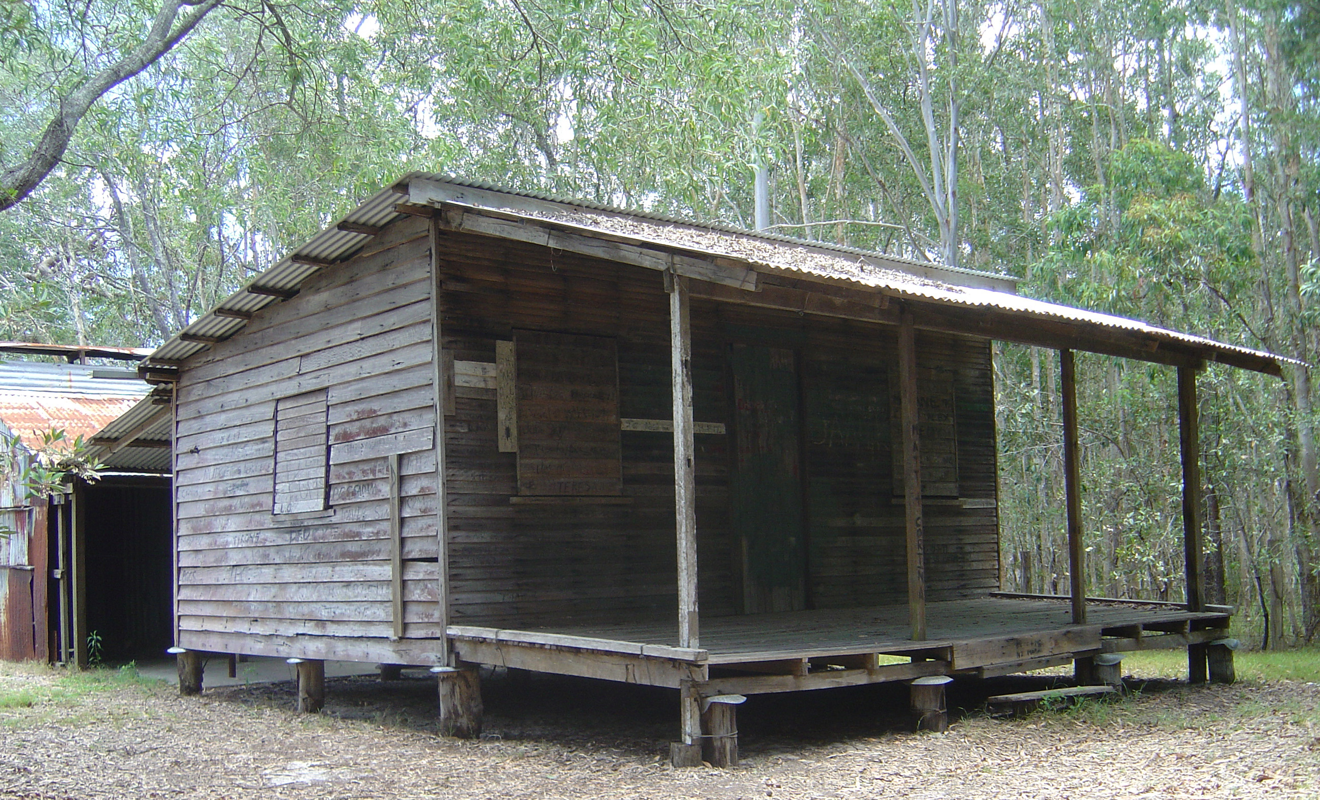
Harry’s Hut (3.7 mi / 6 km W of ocean) © 2006 Rae Allen

Typical DX application with the folded dipole & Degen DE1121 at Harry's Hut © 2014 FM DXing

Typical DX application with the folded dipole & Degen DE1121 at Harry’s Hut (36 ft / 11 m ASL) © 2014 FM DXing

Harry's Hut © 2014 FM DXing

Harry’s Hut © 2014 FM DXing

In September of 2014, this antenna was used at the insect-ridden Harry’s Hut day-use area (above) situated on the western bank of the upper Noosa River. The folded dipole was hand held vertically by the ‘old man’ (dutifully assisting) a few metres above a park bench (inset, right) a short walk from the jetty and canoe landing facilities (below). As a contrast to the peninsula trip recounted above, nothing is notable about this stop! It is included merely as a typical illustration of mobile FM reception that may be ordinarily expected with this antenna (using a narrow filter modified Degen DE-1121 portable recording receiver).

Harry's Hut jetty © 2006 Rae Allen

Harry’s Hut jetty © 2006 Rae Allen

On this evening (during a ‘quick and dirty’ 15 minute listening window available) there was enjoyable jet-reflected scatter from community radio in Byron Bay (coastal S) to public radio in Rockhampton (inland NW) during flat spring conditions (zero ‘tropo’) comprising a scatter range of 390 mi / 627 km. Even the terrific country narrow caster from Bundaberg was audible.

These signals were NOT audible on the Toyota Prado factory double DIN CD/cassette radio, a quality Japanese DSP receiver. Due to superior design, any contemporary car radio typically exhibits greater sensitivity than its portable radio counterpart. For a portable radio to exhibit such out-performance in the field can be attributed to the use of the folded dipole antenna. Such a comparison seemed fair, since both the vehicular antenna and the portable antenna were operated at the equivalent height above ground. Adjacent channel interference was NOT a determining factor in reception.

Any inexpensive portable receiver that features an external FM antenna jack will accommodate a folded dipole (or loop) FM antenna. These radios include the CR-1100, DE-1103 (KA-1103), DE-1121 (KA-1121), PL-660, PL-606 or PL-310ET from the Tecsun manufacturing parent company. Others include the Digitech AR-1748 (bloggers suggest this may be manufactured by Redsun) or the Sangean ATS-505P, to mention a few current models. An antenna adapter (typically a 3.5 mm audio plug to PAL socket) is required. These are available from $4 from electronics retailers. Make no mistake… this writer believes that purchasing a portable receiver which accommodates an external antenna (and the use of a ‘homebrewed’ or commercially-made external antenna) is worth the extra effort!

What about a wire folded dipole?

Wire Dipole inside window © 2013 FM DXing

Wire Dipole inside window © 2013 FM DXing

The above observations are limited to the ‘metal version’ of the half wave folded dipole. It should be acknowledged that a twin lead wire version of this design is widely available. Whilst physically similar to the wire dipole (left) it differs from that ‘pure’ dipole design by having joined conductors and a 300 ohm impedance. Detailed information on the limitations of wire-based antennas appears in the table and references below.

Terk offer three amplified indoor antennas designed solely for FM reception. Amongst these models, the FMPro is based on a folded dipole design. It is weather proofed for use outside. Rival manufacturer Magnum Dynalab offer the SR-100 Silver Ribbon Tunable antenna.

ADVANTAGES DISADVANTAGES
Improved Voltage Standing Wave Ratio (VSWR) measurements at the terminals suggest best efficiency over most other simple antennas, including twin lead (ribbon cable) antennas. More expensive to buy than other simple antennas such as a wire antenna or Rabbit Ears.
Wider bandwidth than a single element dipole. (David Jefferies PhD suggests a sensible single dipole may exhibit a 15% fractional bandwidth). Although the folded dipole is still often classified as a narrowband antenna, the wider bandwidth may be considered a favourable attribute for reception on the FM or digital television bands. May be considered unsightly; beauty is in the eye of the beholder (or ‘beer holder’) of course!
Higher directivity than a single element dipole. Because of its directional characteristics, ideal for mobile reception to null strong, unwanted local stations. Due to higher impedance over a single dipole, requires a balun (usually supplied) if connected to a tuner with a 75 ohm coaxial input only.
Ideal for ‘mating’ with a quality masthead pre-amplifier if using a car receiver or component tuner. Unsuitable for air travel because does NOT fit in standard ports (suitcases).
Easily fits in the cabin of the average sedans (including in the boot). Depending on the size (a function of the wavelength) the copper version may be quite heavy (but effective exercise) if transporting to a summit or forest clearing.
Extremely durable; it will probably outlast one’s portable receiver! Significantly better durability than telescoping rod antennas such as Rabbit Ears.
Easily fits in a bedroom for indoor reception near a window.

As always, the writer has no affiliation with any retail merchant or product manufacturer mentioned. This entry is NOT intended to be construed as an endorsement of any particular product. Prospective buyers should carefully make their own enquiries according to their particular needs and circumstances.

The author wishes to acknowledge the valuable assistance of David in providing his feedback and personal observations of earlier drafts.

Altitude measurements performed with Celestron altimeter calibrated on-site. Calculations performed with Google Earth using ACMA KMZ data.

* Due to abnormally hot & active tropospheric ducting experienced during October & November, the aforementioned copper folded dipole DIY project will now be published (later than originally scheduled) during December in two parts. The writer apologies for the delay in publication. 


ANTENNA SUPPLIERS

D-lemp Communications Limited

Magnum Dynalab

Rescue Electronics Surplus

Terk Antenna Range


ANTENNA TUBING V WIRE EFFICIENCY

Holl_Ands

Rescue Electronics Folded Dipole


ANTENNA MATERIALS

Building antennas from everyday materials

Spark Fun United States

Tapes Online Australia


DIY DESIGNS TO BUILD WITH ALUMINIUM TUBING

Copper or aluminium foil tape dipole

Copper foil tape antenna

Stealth antennas made from conductive foil


DIY DESIGNS TO BUILD WITH ALUMINIUM TUBING

Folded Dipoles

Element diameter considerations


DIY DIPOLES TO BUILD WITH COPPER TUBING

Bruce’s dipole for FM band

Dave’s off-centre single dipole

850 MHz dipole for Wireless Internet

Nepaeric’s dipole for FM band

Single dipole for two metre band amateur radio 

VHF high band dipole for Digital TV

VHF high band & UHF dipoles for Digital TV


DIY ANTENNAS TO BUILD WITH COPPER TUBING

189 MHz yagi for Digital Television (includes dipole)

P2P micro-powered FM broadcast antennas used by uni students in Melbourne (2009)

Simple DIY FM antennas: build an FM loop for about $20

Please consider the risks involved with constructing an antenna before proceeding with any project. The author shall not be liable for any loss or damage whatsoever (including human or computer error, negligent or otherwise, or incidental or consequential loss or damage) arising out of, or in connection with any use or reliance on these instructions.

This blogger is going through an addictive phase of building simple FM antennas. These DIY (Do It Yourself) antenna projects are not scary to contemplate, at all!

DIY driller bear © 2013 Stu_WP

DIY driller bear © 2013 Stu_WP

Each project must meet the following criteria:

  • the antenna must be fun to build;
  • the antenna must be simple & cost effective to build &
  • the antenna must offer objective measurable performance.

The first ‘victim’ is the loop! The construction consists of four quick and easy steps, detailed below.


What is a Loop antenna?

Loop antennas have been used since 1886 as receiving antennas. The loop is often ‘heard from’ but rarely seen!

MW loopstick antenna © 2008 Explain that stuff.com

MW loopstick antenna © 2008 Explain that stuff.com

An AM or MW receiver such as a Walkman, transistor radio or multi-band shortwave receiver often incorporates a loop stick (Ferrite Rod antenna) inside the receiver. This compact & inexpensive antenna is a multi-turn loop antenna wound onto a ferrite core.

The loop in today’s article is entirely different from the well-known loop stick designed for AM stations. For example, the FM loop design is by necessity, much larger in size & only one turn of wire is used in the construction. The FM loop has ‘a lot going for it’, as it features overwhelmingly positive attributes.


Characteristics of the FM Loop antenna

ADVANTAGE DISADVANTAGE
Potential gain of up to 2 decibels compared to a half wavelength dipole. For maximum efficiency, the antenna may be very large for FM.
Exhibits the same radiation pattern as a dipole. Potential mismatch loss. It may be difficult to match loop to 75-76 ohm coaxial feed line as typical loop impedance is higher than a single dipole (70 ohms).
Suitable for indoor installations. The loop is less affected by movement of the human body than other antennas. It is easily moved between rooms without potentially scratching the walls in the process, unlike a yagi antenna. Full wavelength loops may not fit inside small sedans, reducing portability.
Variety of configurations are possible. Choose from multiple shapes!
Variety of orientations are possible. (Please refer to the suggestions on offer by Karl, KA1FSB in the links below).
Circumference may be shortened to ¾ of a wavelength for confined spaces. It may be mounted on window as stealth antenna.
Easy to build & inexpensive to build. (Please see below for four FM loop projects).
Does NOT require a ground plane. By contrast, a vertical telescopic or whip FM antenna requires a large vehicle body! That antenna also tends to exhibit a loss, NOT a gain. (Please refer to the simulations of Holl_ands).
Offers potential on a balcony as a stealth antenna. The loop may be covered with plastic or beach towel. (Please refer to the suggestions on offer by Simone IW5EDI & Mike Thompson in the links below).

Build an FM loop

Completed FM loop on the lawn © 2014 FM DXing

Completed FM loop on the lawn © 2014 FM DXing

Step 1. Perform software calculations (5 minutes)

Karl, KA1FSB offers an on-line calculator. The calculator suggests that for a 102.1 MHz loop, a 3 metre (9.84 ft) circumference is required. This loop exhibits a typical impedance of 102 ohms. The dipole equivalent is 1.4 metres (4.6 ft) long.

Step 2. Buy/beg/steal/borrow the materials (10 minutes)

A flexible copper coil with a length of 3 metres (9.84 ft) was purchased for $20 at a retail hardware store that sells plumbing supplies. The outer diameter is 12.7 mm (1/2 inch). It has been suggested that tubing diameter is not critical for this application.

Coiled copper tubing © 2007 neufcent9

Coiled copper tubing © 2007 neufcent9

Alternative material options: If bending can be performed, other materials such as aluminium may be used. (Steel may not be the optimal choice of antenna material; this higher resistance material exhibits a conductivity as low as 16-17% compared to copper at 92%).

Alternatively, copper or aluminium tape may be used. Copper particle conductivity paint such as CuPro-Cote may be used. Wire may be used.

Roll of soft Copper tubing, coiled © 2009 Apalca

Coiled roll of copper tubing © 2009 Apalca

Optional step: If cutting copper tubing to a specific length is necessary, a cutter may be purchased for about $18 or less. Please ensure the cutter is compatible with the diameter and wall thickness of the copper tubing.

Coaxial cable can be purchased for 70 cents per metre or about $5 for a two metre cable with pre-fitted F-connectors. RG59 or higher grade cable is recommended.

Step 3. Construct the antenna (20 minutes)

Inside or outside (a grassy surface is recommended) bend the copper tubing slowly by hand to form a circle. Forming the circle should take no longer than 15 minutes. Forming a perfect circle is unnecessary!

The completed circular loop is placed onto a non-conductive mast. For this construction, a $2 PVC pipe was used as the mast. The loop was fastened to the mast using plastic cable ties. Two ties are used to secure the top of the antenna to the pole; one tie for the base of the loop.

Step 4. Feedline connection (10 minutes)

The final mandatory step is to solder a short length of coaxial cable to the ends of the loop and connect to a masthead amplifier. (The use of an amplifier with this or any other antenna is optional).

Coaxial cable inputs to loop  © 2014 FM DXing

Coaxial cable inputs to loop © 2014 FM DXing

Soldering the coaxial cable to the ends of the copper tubing requires care to maintain durability. RG59 or thinner specifications of coaxial cable may be the easiest to manage without ‘weighing down’ the loop.

Feedline input to FM loop antenna with ferrite choke © 2014 FM DXing

Feedline input to FM loop antenna with ferrite choke © 2014 FM DXing

Alternatively, aluminium or copper tape may be used as an alternative to fasten the cable to the copper. Large alligator clips are another option.

For this antenna construction, a RG59 coaxial cable with pre-fitted F-connectors was purchased. One end of the cable was cut off & stripped away to reveal the inner conductor & shield. The inner conductor is soldered to one ”leg’ of the loop antenna; the shield of the cable to the other ‘leg’.

The other end (F-connector) was connected to the masthead amplifier. Weatherproofing the connection may be necessary if the antenna will be used on a permanent basis outside.

Feedline input to FM loop antenna with ferrite choke © 2014 FM DXing

Feedline input to FM loop antenna with ferrite choke © 2014 FM DXing

Add-ons: Optional steps that may aid in optimizing the connection can be found in the Impedance Matching section, below.

The possibilities are limitless!

To receive long distance FM reception on the dual band Sangean WR-2 RDS receiver, enthusiast 1963DX constructed a quad FM loop antenna. That loop was optimized for about 109 MHz using copper wire on a wooden frame. Watch the video. Engineer Mike Thompson offers another version. About a decade ago, colleague John Faulkner G1VVP compiled a quarter wavelength version of the FM loop for the Skywaves club website. That design is made using coaxial cable. The original graphics have been mirrored at the Most Useful Information Ever.

Completed FM loop on the lawn © 2014 FM DXing

Completed FM loop on the lawn © 2014 FM DXing


Initial testing

The FM loop is a directional antenna which exhibits gain. Performance is simple yet effective.

When placed inside the house during winter, the antenna will enable reception of the following permanent signals:

  • 80 kW stations to 230 km / 143 mi;
  • 10 kW stations to 221 km / 137 mi &
  • 200 watt translators to 104 km / 65 mi.

Ideally for optimal performance, the antenna would obviously be placed outside. Metal objects inside for example, may cause interactions or obstructions. Outside, this antenna yields:

  • 100 kW stations to 328 km / 204 mi &
  • 3 kW stations to 286 km / 178 mi.

In the field, the FM loop antenna has performed extremely well. To date, the most distant evening spring-time tropospheric scatter reception occurred out to 578 km / 359 mi on an apartment balcony. Detailed field performance and photography may be found at the continually-updated Have Loop, Will Travel entry.

When the antenna is connected to a sensitive car radio or component tuner, the FM loop typically outperforms a Silabs’-based portable FM receiver with the supplied telescoping antenna. Much like a dipole, the FM loop antenna also offers good performance if connected to a portable receiver.

To be fair, crude testing under flat conditions may only offer support to assertions made about potential antenna performance! Objective measurements tend to be more reliable. These characteristics are discussed in the final section, below.


Gain

The quad loop exhibits a maximum of 1.14 decibels gain relative to a dipole (in other words, a 3.27 dBi gain) according to W8JI.

The 2005 edition of the ARRL handbook (reliant on NEC based antenna modelling data) specifies the maximum gain of a full wavelength loop to be 1.35 decibels relative to a dipole (these units are known as dBd).

For modelling comparisons between circular & square VHF loops of different dimensions, please refer to Holl_ands simulations.

What about the performance for this specific loop project? Well, modelling using MMANA-GAL Basic software suggested that maximum gain within the FM band for this loop may be as high as 1.44 dBd. Optimal SWR occurred above 105 MHz.

Comparisons to other domestic antennas

The FM loop may be ideal for long distance FM enthusiasts or listeners with a single fixed external antenna, such as a wideband television antenna.

Completed FM loop on the lawn © 2014 FM DXing

Completed FM loop on the lawn © 2014 FM DXing

A contemporary rooftop-mounted log yagi television antenna (for US channels 6-12 & UHF) will typically exhibit a maximum gain of 1 dBd for reception at the top of the FM band & a loss for stations below 95 MHz. The loop is likely to outperform such an antenna, even on a small mast 1.7 m (5.6 ft) above ground.

The smallest & most inexpensive rooftop FM yagi antenna (3-el FM yagi) will typically exhibit a maximum gain of between 4-5 dBd. For those yagi owners, a secondary antenna such as a loop may be useful where neighbouring electrical interference is affecting the rooftop antenna, the rooftop antenna is fixed in one direction (resulting in only weak signals audible ‘off-the-side’ of the antenna) or for testing purposes in conjunction with the main antenna.

These figures are provided in good faith, based on calculations performed in antenna modelling software & antenna manufacturer data.

Polarization

As the feedline input is entering at the side, this FM loop antenna is vertically polarized. This is one of several configurations to consider.

Impedance matching

Holl_Ands modelled 82-86 MHz & high VHF band circular loops. The modelling suggests impedance varied enormously with frequency.

Various sources suggest that full wavelength loops may exhibit a typical impedance of roughly 102 – 115 ohms. In chapter four of his book, electrical engineer Walton C. Gibson suggests a circular loop exhibits an impedance of 140 ohms at resonance. This impedance is about half that of the folded dipole.

Completed FM loop on the lawn © 2014 FM DXing

Completed FM loop on the lawn © 2014 FM DXing

Use of this antenna with standard 75 ohm feedline may cause a potential impedance mismatch. Mismatch loss may arise, where signal is reflected back to the antenna.

It could be argued that the impedance mismatch between (say) 140 ohms and 75 ohms has a negligible effect on ultimate received signal strength. Therefore, inserting a 1:1 current balun ‘home brewed’ from coaxial cable or ferrite suppression chokes represent two optional steps to consider. (Please refer to Brian’s website below). After these chokes have been inserted, a masthead amplifier may help compensate for potential mismatch loss.

Dimensions

The single dipole equivalent to this loop (with the same element diameter) is roughly 1.4 metres long, if measured tip to tip. A folded dipole requires slightly longer dimensions, typically 2%. Typically, the larger the tubing diameter, the greater is the potential bandwidth of an antenna. Element thickness is an important characteristic.

1/2 inch (12.7 mm) copper annealed coil was used to construct this loop antenna simply because the outlay was $10 cheaper than the same length of 3/4 inch (19.05 mm) coil! There were at least eight copper tubing diameters readily available to buy.

The following diameters of copper tubing are frequently used to construct circular loop antennas on the six metre, FM & high VHF broadcast bands:

  • 3/8 inch (13.06 mm);
  • 1/2 inch (12.7 mm) tubing or
  • 1/4 inch (6.35 mm).

A final word: Mounting

As pictured, a satellite tripod is used to secure this FM loop antenna. These are priced between $50 – $70. A more inexpensive garden sprinkler tripod ($30) also works. Alternatively, mounting the FM loop inside on a large window may also be feasible. The weight of the copper tubing (dependent on the chosen thickness) will need to be secured to the window, as to ensure the antenna does not fall over!


Reference books

Antenna Basics by Christof Rohner et. al.

Antenna Design for Mobile Devices by Zhijun Zhang

Method of Moments in Electromagnetics by Walton C. Gibson

Radio Antenna Engineering by Edmund A. Laport


Reference websites

Antenna-Theory.com

Brian, K6STI

Frits, PAØFRI

Simone, IW5EDI

‘Yukon John’, KL7JR


Antenna software

John, VK5DJ

MMANA-GAL


Lecture notes & Powerpoint slides

A practical approach to HF-VHF antennas, plus antenna myths & mysteries by Terry Graves, K7FE

Computer antenna modelling simplified by Larry J. LeBlanc, KE5KJD

Loop Antenna characteristics by Pat Donohoe PhD


This entry was last updated during December 2014.