Analogue line level recording with inexpensive handheld MP3 players

Recording with software on a computer provides an alternative to hand held MP3/WMA recorders. In this article, the recording potential of inexpensive hand held records will be examined.

Hand held recorders may suffer from a number of problems. The most obvious limitations of hand held MP3/WMA recorders are likely to be:

* Poor battery life. Sure, this can be rectified by fitting a replacement, but doing so can be a potentially risky & difficult task – assuming one can even find a replacement battery!

* Limited storage capacity for long recordings. Fixed capacity recorders force users to only keep a very small selection of music or videos on the player, otherwise there is inadequate recording space available when needed.

Other potential headaches experienced with portable MP3/WMA recorders include:

* Automatic Level Control (ALC) is implemented for recording, which is not ideal for all programme material. ALC artificially restricts the dynamic range of the recording. Limiting dynamic range is considered undesirable for music, although it is applied widely to radio broadcasts. A pair of RCA Line Level Audio Attenuators may be required to ‘tame’ audio output levels from analogue components (e.g. Harrison Labs’ manufacture 3, 6 & 12 dB models, which retail from $34).

* Encoding quality. Line-in recording is frequently restricted to relatively low bit rates such as 128 kbps, 160 kbps or 192 MP3 compressed audio recording. These bit rates are not ideally suited for recording music. Gabriel Bouvigne recommends 256 kbps MP3 as a minimum encoding rate for music. Today, even sub-$100 cellular phones support lossless FLAC audio. Does compressed audio files (such as open source MP3, Apple’s AAC or Microsoft’s WMA) still offer relevance?

Creative & Samsung Hand held MP3 Players

Perhaps two of the most suitable MP3 players for recording include the Creative Muvo Vidz & Samsung YP-T8 MP3 players. Both are available in 1 GB capacities. This capacity means these devices are capable of performing recordings from analogue components lasting over 11 hours at 192 kbps MP3 (their highest recording bit rate). That would fill over seven 90 minute cassettes. Unfortunately, these players are extremely rare to find & cost over $80 in the second hand market.

1 GB capacity Creative Zen Neeon 2 models fit 16 hours of recordings at 128 kbps WMA (their highest recording bit rate). These are readily available, refurbished by the manufacturer priced from $45 (1 GB) up to $85 (4 GB).  It is difficult to overlook the fact that the 4 GB model will fit an impressive 66 hours of recordings (128 kbps WMA), but Creative’s Zen Neeon series cannot be recommended by the author. This is due to unreliability of the hardware, in particular the widespread reports of hard drive failures. The author’s Neeon 1 model will not start up.

Olympus Hand held Recorders

The Olympus WS-832 & WS-833 (from $160 new) record with PCM format as well as 256 kbps MP3 but probably audibly wreck bass response (e.g. timpani, kick drum & bass guitar) because of a sharp 40 Hz cut-off. The specified PCM recording frequency response is only 40 Hz – 21 kHz. Such a shame, because these voice recorders also feature fully adjustable recording level control.

Mini Disc Portable Recorders

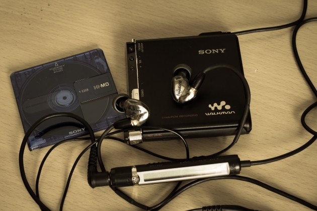
Mini Disc portable recorders which use ATRAC implementations also suffer from similar restrictions on quality like MP3/WMA. The exception is if one owns the relatively rare Hi-MD recording models (examples, pictured below) & can also readily source affordable discs.

dietrich_liao_2006_mz-rh10

Sony MZ-RH10 © 2006 Dietrich Liao.

SONY DSC

Sony RH-1 © 2012 Jaen Yu.

Example: Recording with Zen V Plus & Samsung Yepp T7

Personally, the writer has enjoyed immensely recording on these tiny devices over the last decade. The primary advantages are due to their size. An honest evaluation of their performance is warranted.

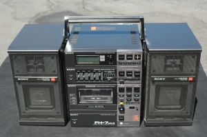
In theory, portable digital recorders should perform better recordings than modern compact cassette boom boxes. Modern boom boxes incorporate poor quality recording heads with rapidly falling treble response over 10 kHz, not to mention poor wow & flutter performance (due to poor quality generic mechanisms) compared to the relatively high quality found in boom boxes during the 1980s & 1990s. During this period, some of these at the high-end boom boxes such as the 1990 model AIWA Strasser CSD-SR8 (photos here & here) featured Dolby C & Dolby B noise reduction as well as manual recording level control. If functional, these high-end boom boxes command very high prices today on auction sites.

Take, for example the Creative Zen V series recorders which are no longer manufactured, but still sold (currently priced from $80, manufacturer refurbished).

OLYMPUS DIGITAL CAMERA

Zen V © 2007 Brian Barnett.

When launched in 2006 for $230 USD the Creative Zen V Plus received favourable reviews. The playback audio quality was very good on the Zen V series with low levels of noise & distortion reported during measurements. The Zen V series uses the Media Transfer Protocol (MTP) to transfer video & audio files (including uncompressed PCM, as well as compressed MP3/WMA) in Microsoft Windows operating systems.

Creative’s Zen V players (as well as the Zen Neeon 2, mentioned earlier) would be more useful if the player did not encode line-in recordings in 160 kbps WMA format. Today, WMA offers less playback support than MP3 & AAC files so the future is not rosy.

Exacerbating this, is the fact WMA recordings are unsupported by loss less MP3 software editors such as MP3DirectCut if one needs to edit the recording. Converting recordings to PCM alleviates this but doing so offsets the primary advantage of compressed audio, the small file size!

josh_bancroft_2005_samsung_yepp

Samsung YEPP YP-T7 recorder in the bottom left © 2005 Josh Bancroft.

The other problems encountered when analyzing software measurements suggested that hiss & clipping may be problematic when recording on the Creative Zen V Plus & Samsung YEPP (Young Energetic Personal Passinate) model T7, pictured above. A Sangean PR-D8 (chosen because it supports 192 kbps MP3 line-in encoding) was used to double check any inconsistencies found with recordings made on the Zen & YEPP MP3 players.

Hiss

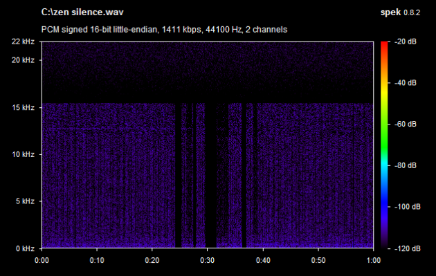
Surprisingly, recordings on the Zen exhibited 15 dB more high frequency noise (hiss) in a recording of silence compared to one made on a laptop sound card. These (admittedly imperfect) software measurements were of noise floor, made in Root Mean Square (RMS) amplitude. Another crude inspection using the meter (maximum range: -96 dB) suggested approximately 10 dB more noise in the Zen recording of silence.

Recording nothing ain't so silent on the Zen! © 2016 FM DXing.

Recording nothing ain’t so silent on the Zen! © 2016 FM DXing.

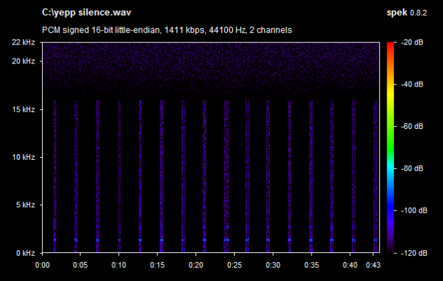
The Samsung YEPP recordings exhibited less than 3 dB more noise in recordings of ‘silence’ than the sound card which was expected – so very close to the performance of the sound card. Of three hand held recorders by different manufacturers, the YEPP outperformed all others in tests.

Recording nothing ain't so silent on the YEPP either! © 2016 FM DXing.

Recording nothing ain’t so silent on the YEPP either! © 2016 FM DXing.

Regardless, the A-weighted Signal to Noise Ratio (S/N) figures for analogue (line-in) recording from the sophisticated Wolfsen Microelectronics, Telechips, Texas Instruments & SigmaTel’s D-Major ‘codec’ Integrated Circuits (ICs) utilized inside these MP3 players do suggest 80-85 dB as minimum figures. But the noise is higher than the IC measurements because other hardware (such as LCD screens & poor component shielding) in the players may produce additional noise – perhaps even the encoding software. Hence, the actual real world S/N figures for recordings is typically lower than the ‘codec’ figures.

At this point it may be useful to compare more closely these low-cost digital recordings with their vintage analogue counterparts. The A-weighted Signal to Noise Ratio minimum figures for compact cassette tape recordings are as follows: tape recordings encoded with the commonly found Dolby B provide 68 dB S/N. The high-end, (but both less compatible & prevalent) Dolby C provides 78 dB S/N. The relatively rare high-end Dolby S provides 80 dB. There is likely to be negligible variation between ‘Dolbyized’ recording decks.

neil-_2009_jvc

JVC cassette deck © 2009 Neil.

frankpr_2014_gxc-760d

1978 vintage Akai GXC-760D cassette deck © 2014 FrankPR.

Modern low-end compact cassette recorders may not offer noise reduction provision, including many portable boom boxes & light weight mini systems. In fact, the new Prince re-issue cassette albums that were manufactured in the United States in latter half of 2016 are not recorded with Dolby B noise reduction for this reason; unlike vintage pre-recorded cassettes.

Yamaha PC-8 portable system with Dolby B & C noise reduction

Yamaha PC-8 portable system with Dolby B & C noise reduction.

sony-fh7-mkii

Sony FH-7 MkII portable system with Dolby B & C noise reduction.

Without noise reduction, the minimum Signal to Noise Ratio (A-weighted) is 58 dB, even worse on some machines with cheap mechanisms with figures as low as 52 dB S/N. In theory, these inexpensive modern tape recorders should create recordings with considerably higher hiss than is possible with digital recording using the aforementioned ‘codec’ ICs.

Clipping

Worse than noise added, a test recording from a compact disc component (original CD pressing of Roy Orbison’s Mystery Girl) showed clipping  in all software & also failed the ABX recording level tests, with the recordings on both the Zen & YEPP peaking in excess of -3 dBFS. This is despite the recording being made well below the peak (red coloured) levels on the recording level display. 3-6 dB RCA Line Level Audio Attenuators do tame output levels so the clipping does not occur, but are an unnecessary expense.

The process of encoding to compressed audio formats may cause clipping, so turning the input volume down may not necessarily address the problem in every instance. In those circumstances, the clipping should be be tolerated – consider it to be a normal artifact of the encoding process. Be that as it may, in the few tests performed with these recorders, clipping could be entirely avoided in the WMA or MP3 by simply lowering the recording volume using an in-line Level Attenuator.

Frequency Response 

Let’s examine the frequency response of recordings in detail now. Particular detail will be paid to how analogue portable recorders perform as well, which will serve as a benchmark.

The encoder on the Zen will also discard frequencies above the sharp 15.5 kHz cut off so is most suited for FM radio recording. FM broadcasts exhibit approximately the same cut off. Frequencies also sharply rolled off after 16 kHz on the YEPP recordings.

Note that for digitally recording local FM broadcasts, the ADS Tech RDX-155 ($20, new) is the better route, due to the provision of lossless 192 kHz sample rate PCM recording. This Silicon Labs’ SI4701 tuner (marketed as ‘Instant Radio’, above) is a USB computer tuner which requires antenna modifications (including soldering) for connection to a rooftop antenna.

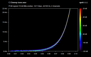
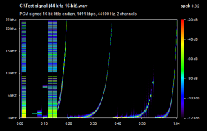
Two test signals were recorded in the Zen. On the left is the original, on the right is the copy. This spectral analysis illustrates the ability of the recording to capture the original.

sweep-zen

test-signaltest-signal-zen

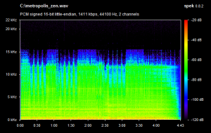
In addition, an eighties rock song was recorded in the Zen.

metropolismetropolis-zen

These measurements are not considered to be problematic; many quality cassette recorders gently roll off content after 18 kHz. It is often suggested that unless one makes recordings with considerable of gong & cymbal percussive content, such high frequency roll off may not even be noticeable.

Vintage JVC one-piece boom box © 2011 Neil.

Vintage JVC one-piece boom box © 2011 Neil.

One low-end boom box tested (manufactured in the late nineties) exhibited little high frequency response after 14 kHz, whilst one high-end boom box tested (manufactured in the mid-eighties) lasted beyond 17 kHz. These had been professionally serviced with new belts fitted as necessary, the digital recorders do not require ongoing servicing.

Below is an example of a high-end boom box recording using Dolby B noise reduction & a medium grade TDK AD tape. Again, on the left is the original, on the right is the copy. Strikingly, the cassette recording significantly outperforms the Zen recording, shown above. But remember this machine has been well maintained; vintage analogue equipment requires ongoing attention if it is to continue performing close to the original manufacturer specifications.

jvc-cd-source-same-old-scenejvc-same-old-scene

Modern boom boxes offer considerably worse compact cassette recording performance than these (above) examples. For instance, observe (below) the performance of a regularly serviced, low-end boom box compared to the Zen digital recording. Whilst there is slightly higher frequency response on the cassette recording, this analogue quality improvement is offset by more hiss (evident in blue, above 12 kHz) than the Zen digital recording, as the low-end boom box recorder provides no noise reduction. In fairness, compression artifacts affect the digital recording (due to low 160 kHz encoding bitrate). Depending on the genre of music being recorded, these digital noises may be as irritating to listen to as audible hiss. It is a matter of personal preference as to which of these two low quality recordings is more natural sounding to listen to.

panasonic-selling-the-dramazen-selling-the-drama

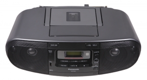
Modern boom boxes (marketing pictures appear below) include the Panasonic RX-D55 (from $182, new) & Sony CFD-S50 (from $117, new).

panasonic-rx-d55

Panasonic RX-D55 boombox.

sony-cfd-s50

Sony CFD-S50 boombox.

Extremely poor recording performance with modern boom boxes is probably because the demand for quality is not strong, like it was in the eighties & nineties. Although currently fashionable amongst indie recording artists, these plastic boom boxes cannot be even recommended for the simple task of playback of pre-recorded cassettes! Today, manufacturers’ research & development priorities are likely to be focused on digital recording.

Final comments

It is hard to dispute that these portable hand held recorders can offer immense convenience & are likely produce higher fidelity recordings than modern low-end boom boxes. Firstly, a laptop or boom box recorder is much larger in size. Secondly, laptops must be regularly maintained with software & perhaps to a lesser extent, hardware upgrades. Boom boxes also require maintenance such as regular head cleaning & very rarely, belt replacement. Ongoing maintenance for these hand held recorders is negligible. Those commitments might include regularly charging the battery & very rarely, updating firmware!

However, the testing of Zen & YEPP indicated evidence of noisy or poor quality A-D conversion in these recorders, compared to even the most basic on board sound cards found in computers. Audio clipping is also a significant potential problem, especially for careless users. The Automatic Level Control cannot be blindly relied upon during recording. These factors potentially contribute to noisy, harsh-sounding or distorted recordings.

Accordingly, the next topic for discussion is the use of simple software for portable recording on superseded or surplus laptops. It is suggested that recording with a computer may allow better quality recordings than hand held recorders because of the less restrictive encoding options, full adjustment of recording levels & options to plug in high-end external sound cards into the computer. But it can be tricky to find free software that simplifies, rather than unnecessarily complicates the process!

Simple DIY FM antennas: Building a Folded Dipole Pt.1

Overview

These simple antenna construction projects are primarily designed to be fun to encourage more interest in long distance FM reception, DAB+, digital television or the two metre band amateur radio. Once again, the additional criteria (or criterion) are that an antenna design should offer simplicity in construction & measurable performance.

Copper pieces © 2006 FreshElectrons

Copper pieces © 2006 FreshElectrons

Building a folded dipole antenna is only marginally more difficult to construct than the popular DIY circular FM loop project. Again it’s an all copper affair! Annealed copper tubing was chosen as antenna material for the earlier project.

For construction of the folded dipole, inflexible copper pipe is used. 90 degree ‘elbows’ are chosen for the joins which means no special tools are required to bend the copper.

To aid readability, this construction article is published in two parts. The focus in this article is on getting everything ready for the build. The second part is the ‘home stretch’, the fun part with a step-by-step guide to building the antenna.

Why build a folded dipole?

Unlike a multiple element yagi antenna, a folded dipole may perform satisfactorily under challenging indoor reception scenarios where multiple metal signal reflections often exist.

Copper tubing prior to construction  © 2014 FM DXing at WordPress

Copper tubing prior to construction © 2014 FM DXing at WordPress

The straight copper pipe must be cut into five pieces. The final step is to glue the antenna together so it does not fall apart. Antennas don’t perform well in pieces! Although gluing may not be considered mandatory it is recommended, especially if the antenna will be mounted vertically. Otherwise, the heavy pieces of copper pipe may fall to the floor.

The most important part of the construction is getting the dimensions reasonably accurate for the required frequency. Once that step is complete, then one proceeds with the fun ‘hands on’ part, which is cutting the copper pipes and gluing the folded dipole together!

Project cost

The author spent $45.50 to build this project. This figure might be considered an indicative minimum cost.

For the apartment dweller whose tool shed is likely to be entirely bare, the maximum cost of the entire project is $86. Perhaps that maximum cost might seem expensive? But another way of looking at it is to consider that many of the materials (such as a quality tube cutter, Wire Glue adhesive, tape measure, surplus ‘off-cuts’ of copper tubing, PVC pipe & marker pen) can be used for years to come in future projects.

Metal pipe cutter 6-35 mm © 2012 Robert & Mihaela Vico

Metal pipe cutter 6-35 mm © 2012 Robert & Mihaela Vico

Copper elbows © 2012 Robert & Mihaela Vico

Copper elbows © 2012 Robert & Mihaela Vico

Cost projections exclude discretionary items such as mounting tripods & masthead preamplifiers. Buying copper tube in 1.5 metre / 59 inch increments (the shortest lengths the author has seen at the retail level) may increase the tabulated representative price of tubing by as much as 23%. To minimize cost, it is recommended to purchase the longest piece of ¾ inch copper pipe one can reasonably transport home and then cut it into the lengths required.

Feedline is a mandatory additional cost. Its cost is likely to be insignificant. Obviously, cost will vary with the length and type of feedline required. For detailed discussion, please refer to the feedline section in part two of this publication.

ESSENTIAL MATERIALS COST PLACE OF PURCHASE (PICKUP)
¾ in diameter straight copper tube x 3 m OR $25 OR Discount hardware retailer
¾ in diameter straight copper tube x 4 m $33 Discount hardware retailer
Store brand tube cutter OR $8 OR Discount hardware retailer
Brand name tube cutter (recommended) $17.50 Discount hardware retailer
Copper elbows to suit ¾ in tube x 4 pcs $10 Discount hardware retailer
Alligator clips with 12mm jaw x 2 pcs $2.50 Electronics retailer
OPTIONAL MATERIALS COST PLACE OF PURCHASE (PICKUP)
Wire Glue $10 Electronics retailer
Permanent ink marker pen $1.50 Discount hardware retailer, supermarket or newsagent
F-type outdoor balun $5 Electronics retailer or Discount hardware retailer
Store brand tape measure $3 Discount hardware retailer
Highest pressure grading (thickness) PVC pipe x 2 m $3.80 Discount hardware retailer

Before building, one must ascertain the dimensions

According to Martin E. Meserve K7MEM, the most important measurement for the folded dipole is its total length, measured tip to tip.

The recommended dimensions for a folded dipole can be calculated using simple software or by using raw calculations. A useful rule of thumb is that a folded dipole is typically 2% longer than a single dipole.

There are at least four ways of obtaining the measurements. One recommended way is to use software calculations. This software provides precise measurements for constructing a folded dipole. The only input required is the resonant frequency of the antenna & the diameter of the tubing. The software is simple to use.

Option 1. Download VK5DJ’s Yagi Calculator software. Use the Design Yagi function.

The software will enable one to manipulate the antenna design with MANA-GAL Basic antenna modelling software to allow further analysis or optimization.

Option 2. Download Al Legary VE3SQB’s software Yagi-Uda Antennas.

Option 3. Use the on-line Folded Dipole antenna calculator. Unfortunately this calculator only allows the calculation of dimensions for tubing diameters of 10.2 mm, but its calculations may be considered a useful rule of thumb.

Software calculations  © 2014 FM DXing at WordPress

Software calculations © 2014 FM DXing at WordPress

Option 4. The lazy way! An alternative route is to copy. That’s right, simply copy the dimensions of a commercially made aluminium folded dipole from an FM yagi. As always, it is recommended not to deviate from the dimensions, including the use of an identical thickness of tubing.

A commercial design made from aluminium

The following dimensions were taken from commercial folded dipole found in a 5-element FM yagi.

ANTENNA CHARACTERISTIC SPECIFICATION
Material Aluminium tubing
Theoretical Gain 2.14 dBi
Aluminium Length – Longest piece 1.455 metres (57.3 inches)
Total Length – measured tip-to-tip 1.54 metres (60.6 inches)
Straight Tubing Diameter Approximately 13 mm (more likely 12.7 mm)
Spacing Gap between the dipole ends – ‘Feed Gap’ in centre of antenna 25 mm
Spacing Gap between the tubing – Horizontal section separation 50 mm

An example construction made from copper

Using software calculations, the author constructed the following dipole. She appears in the photographs in this series.

ANTENNA CHARACTERISTIC SPECIFICATION
Material Copper tubing
Gain (theoretical) 2.14 dBi
Maximum Gain (theoretical modeling in free space) 0.32 dBd (2.47 dBi)
Copper Length – Longest piece 1.5 metres (59 inches)
Bandwidth (theoretical modeling in free space, SWR < 1.5) 85.9 – 98.7 MHz (12.7 MHz)
Total Length – measured tip-to-tip 1.54 metres (60.6 inches)
Straight Tubing Diameter 19 mm
Bend Diameter 20 mm
Spacing Gap between the dipole ends – ‘Feed Gap’ in centre of antenna 50 mm
Spacing Gap between the tubing – Horizontal section separation 50 mm

Terminology

What was that? Did I hear you ask what the #$%^ is the ‘feed gap’? What on earth is ‘tip-to-tip length’? Relax, in his introduction, Martin K7MEM offers a thorough explanation of the terminology used. Antenna gain is often quoted with reference to the half wavelength dipole, that is dBd.

Folded dipole terminology © 2014 FM DXing at WordPress

Folded dipole terminology © 2014 FM DXing at WordPress

Modelling

For those who enjoy software modelling, Graham Daubney F5VHX cautions that the folded dipole may be difficult to model accurately in software. David Jefferies PhD suggests, ‘Any modelling process needs careful validation by measurements’.

Build a copper folded dipole antenna easily without soldering © 2015 FM DXing at WordPress

Build a copper folded dipole antenna easily without soldering © 2015 FM DXing at WordPress

Indicative specifications

For comparative purposes, the author examined the on-line specifications of eight aluminium or stainless steel folded dipoles marketed for FM broadcast applications. In these models for sale, maximum forward gain figures were 0, 1 or 2 dBd & front to back ratios were 4-7 dB. Those manufacturers purporting to offer the highest specifications typically took into account overall performance when the antenna was mounted vertically on a horizontal conductive pole. There was some standardization and simplicity to be found in the crude analysis nonetheless; a typical element diameter was 19 mm & maximum bandwidth 10% of the centre frequency!

Bandwidth is typically measured using VSWR (Voltage Standing Wave Ratio). Rescue Electronics tested the bandwidth of their FM folded dipole designed for FM reception. The SWR was measured at less than 2 (a mismatch loss of only 0.51 dB, calculated at Antenna Theory) between approximately 80-110 MHz.

Holl_Ands has provided SWR modelling plots for his folded dipole (which includes FM coverage) which are invaluable for comparisons between copper tubing diameters.

Stay tuned for part two… it is expected to be published shortly… but the author is too distracted, ‘at the trough’ trying to emulate the DX pig!!!

Further reading

Bandwidth of the Folded Dipole by Natalia K. Nikolova PhD

Bandwidth Explained at Antenna Theory.com

Copper FM J-pole Antennas by Michael Martens, KB9VBR

Simple FM antennas: Introducing the Half Wave Folded Dipole

Cost:  From $ 45-75

Length: Approximately 137 cm (54″)

The Half Wave Folded Dipole comprises two elements of typically Aluminum Alloy construction. The Folded Dipole forms the active (or driven) element in a Yagi-Udi array.

Folded dipole for DAB+ bands © 2013 Digitek

Folded dipole for DAB+ bands © 2013 Digitek

How is it used?

This directional antenna is typically mounted ‘broadside’ to the desired transmitter. Experimenters may choose to add additional dipole elements or incorporate reflectors and directors.

How do I buy one?

If looking to purchase one, there are several options:

  • Remove this element from an inexpensive FM yagi. Before purchasing a yagi to ‘harvest’, please check with the retailer or manufacturer to ensure that the element can be removed; on some retail FM antennas (including the Matchmaster & Hills three element FM yagis) the folded dipole can NOT be physically detached.
  • Rescue Electronics Surplus of Connecticut custom manufactures a ceiling-mounted folded dipole. This antenna is ideal for bedrooms; cost is from $99 with worldwide shipping possible.
  • D-lenp of China manufacturers a two element FM yagi with detachable folded dipole. Cost is $25 plus shipping. Five element varieties are also available.

How do I make one?

At the end of this article there are links to Do It Yourself (DIY) antennas that enthusiasts or radio amateurs have constructed with copper tubing for FM broadcast, digital television & even 850 MHz wireless internet reception!

A folded dipole for FM may be constructed with 19 mm (0.75″) square tube aluminium extrusions or even 6, 8 or 10 mm round tube extrusions.  The choice of round tubing is recommended. Although one metre (3.3 ft) long extrusions (at several of these diameters) are widely advertised for a few dollars each from a major hardware retailer, it is usually necessary to make a custom cut of the appropriate length.

To determine the required lengths for each of the three sections of the folded dipole, please consult an on-line dipole antenna calculator or a step-by-step guide to FM yagi construction. During October*, a step-by-step DIY project will be published on this blog as part of this series on simple FM antenna building. Readers can easily and inexpensively make their own folded dipole for FM reception from copper tubing.

A potentially easier solution than the use of aluminium or copper tubing is to construct a folded dipole (or a standard single dipole) from copper or aluminium foil tape attached to a round tube PVC pipe. And better still; the total cost is far less than a round of drinks with a few lads at The Local.

Is it suitable for field trips?

Absolutely! (Most antennas are, of course but the lighter and smaller to carry the better!)

Half Wave Folded Dipole & suppression choke in sedan © 2013 FM DXing at WordPress

Half Wave Folded Dipole & suppression choke in sedan © 2013 FM DXing

How does it perform in the field?

Whenever this writer ventures into the mountains, this antenna is employed since it outperforms the factory monopole in the car. Whilst this antenna design has long been studied using computer modelling by researchers, empirical observations in the field are (hopefully) a bit more colourful for readers!

Redcliffe foreshore © 2014 Andrew Sutherland

Redcliffe foreshore © 2014 Andrew Sutherland

One of the most rewarding mobile reception achieved with this antenna (above) was rare tropospheric ducting from Nouvelle Caledonie during September of 2013, whilst parked on an unobstructed peninsula (left). Granted, even with a 19 decibel masthead signal amplifier employed in this scenario, these signals were extremely weak! Nonetheless, the bottom line is that the folded dipole antenna offers an enormous potential for any receiving application.  (If reading about mobile mountain DX fun previously published on this blog, please remember that the half wave folded dipole antenna was employed on these ‘day trips’ without exception).

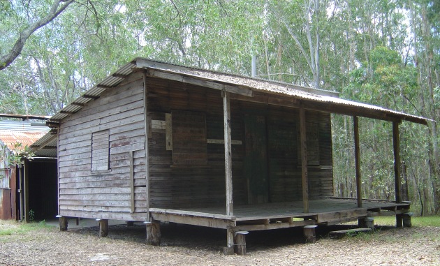
Harry's Hut © 2006 Rae Allen

Harry’s Hut (3.7 mi / 6 km W of ocean) © 2006 Rae Allen

Typical DX application with the folded dipole & Degen DE1121 at Harry's Hut © 2014 FM DXing

Typical DX application with the folded dipole & Degen DE1121 at Harry’s Hut (36 ft / 11 m ASL) © 2014 FM DXing

Harry's Hut © 2014 FM DXing

Harry’s Hut © 2014 FM DXing

In September of 2014, this antenna was used at the insect-ridden Harry’s Hut day-use area (above) situated on the western bank of the upper Noosa River. The folded dipole was hand held vertically by the ‘old man’ (dutifully assisting) a few metres above a park bench (inset, right) a short walk from the jetty and canoe landing facilities (below). As a contrast to the peninsula trip recounted above, nothing is notable about this stop! It is included merely as a typical illustration of mobile FM reception that may be ordinarily expected with this antenna (using a narrow filter modified Degen DE-1121 portable recording receiver).

Harry's Hut jetty © 2006 Rae Allen

Harry’s Hut jetty © 2006 Rae Allen

On this evening (during a ‘quick and dirty’ 15 minute listening window available) there was enjoyable jet-reflected scatter from community radio in Byron Bay (coastal S) to public radio in Rockhampton (inland NW) during flat spring conditions (zero ‘tropo’) comprising a scatter range of 390 mi / 627 km. Even the terrific country narrow caster from Bundaberg was audible.

These signals were NOT audible on the Toyota Prado factory double DIN CD/cassette radio, a quality Japanese DSP receiver. Due to superior design, any contemporary car radio typically exhibits greater sensitivity than its portable radio counterpart. For a portable radio to exhibit such out-performance in the field can be attributed to the use of the folded dipole antenna. Such a comparison seemed fair, since both the vehicular antenna and the portable antenna were operated at the equivalent height above ground. Adjacent channel interference was NOT a determining factor in reception.

Any inexpensive portable receiver that features an external FM antenna jack will accommodate a folded dipole (or loop) FM antenna. These radios include the CR-1100, DE-1103 (KA-1103), DE-1121 (KA-1121), PL-660, PL-606 or PL-310ET from the Tecsun manufacturing parent company. Others include the Digitech AR-1748 (bloggers suggest this may be manufactured by Redsun) or the Sangean ATS-505P, to mention a few current models. An antenna adapter (typically a 3.5 mm audio plug to PAL socket) is required. These are available from $4 from electronics retailers. Make no mistake… this writer believes that purchasing a portable receiver which accommodates an external antenna (and the use of a ‘homebrewed’ or commercially-made external antenna) is worth the extra effort!

What about a wire folded dipole?

Wire Dipole inside window © 2013 FM DXing

Wire Dipole inside window © 2013 FM DXing

The above observations are limited to the ‘metal version’ of the half wave folded dipole. It should be acknowledged that a twin lead wire version of this design is widely available. Whilst physically similar to the wire dipole (left) it differs from that ‘pure’ dipole design by having joined conductors and a 300 ohm impedance. Detailed information on the limitations of wire-based antennas appears in the table and references below.

Terk offer three amplified indoor antennas designed solely for FM reception. Amongst these models, the FMPro is based on a folded dipole design. It is weather proofed for use outside. Rival manufacturer Magnum Dynalab offer the SR-100 Silver Ribbon Tunable antenna.

ADVANTAGES DISADVANTAGES
Improved Voltage Standing Wave Ratio (VSWR) measurements at the terminals suggest best efficiency over most other simple antennas, including twin lead (ribbon cable) antennas. More expensive to buy than other simple antennas such as a wire antenna or Rabbit Ears.
Wider bandwidth than a single element dipole. (David Jefferies PhD suggests a sensible single dipole may exhibit a 15% fractional bandwidth). Although the folded dipole is still often classified as a narrowband antenna, the wider bandwidth may be considered a favourable attribute for reception on the FM or digital television bands. May be considered unsightly; beauty is in the eye of the beholder (or ‘beer holder’) of course!
Higher directivity than a single element dipole. Because of its directional characteristics, ideal for mobile reception to null strong, unwanted local stations. Due to higher impedance over a single dipole, requires a balun (usually supplied) if connected to a tuner with a 75 ohm coaxial input only.
Ideal for ‘mating’ with a quality masthead pre-amplifier if using a car receiver or component tuner. Unsuitable for air travel because does NOT fit in standard ports (suitcases).
Easily fits in the cabin of the average sedans (including in the boot). Depending on the size (a function of the wavelength) the copper version may be quite heavy (but effective exercise) if transporting to a summit or forest clearing.
Extremely durable; it will probably outlast one’s portable receiver! Significantly better durability than telescoping rod antennas such as Rabbit Ears.
Easily fits in a bedroom for indoor reception near a window.

As always, the writer has no affiliation with any retail merchant or product manufacturer mentioned. This entry is NOT intended to be construed as an endorsement of any particular product. Prospective buyers should carefully make their own enquiries according to their particular needs and circumstances.

The author wishes to acknowledge the valuable assistance of David in providing his feedback and personal observations of earlier drafts.

Altitude measurements performed with Celestron altimeter calibrated on-site. Calculations performed with Google Earth using ACMA KMZ data.

* Due to abnormally hot & active tropospheric ducting experienced during October & November, the aforementioned copper folded dipole DIY project will now be published (later than originally scheduled) during December in two parts. The writer apologies for the delay in publication. 


ANTENNA SUPPLIERS

D-lemp Communications Limited

Magnum Dynalab

Rescue Electronics Surplus

Terk Antenna Range


ANTENNA TUBING V WIRE EFFICIENCY

Holl_Ands

Rescue Electronics Folded Dipole


ANTENNA MATERIALS

Building antennas from everyday materials

Spark Fun United States

Tapes Online Australia


DIY DESIGNS TO BUILD WITH ALUMINIUM TUBING

Copper or aluminium foil tape dipole

Copper foil tape antenna

Stealth antennas made from conductive foil


DIY DESIGNS TO BUILD WITH ALUMINIUM TUBING

Folded Dipoles

Element diameter considerations


DIY DIPOLES TO BUILD WITH COPPER TUBING

Bruce’s dipole for FM band

Dave’s off-centre single dipole

850 MHz dipole for Wireless Internet

Nepaeric’s dipole for FM band

Single dipole for two metre band amateur radio 

VHF high band dipole for Digital TV

VHF high band & UHF dipoles for Digital TV


DIY ANTENNAS TO BUILD WITH COPPER TUBING

189 MHz yagi for Digital Television (includes dipole)

P2P micro-powered FM broadcast antennas used by uni students in Melbourne (2009)

Simple DIY FM antennas: build an FM loop for about $20

Please consider the risks involved with constructing an antenna before proceeding with any project. The author shall not be liable for any loss or damage whatsoever (including human or computer error, negligent or otherwise, or incidental or consequential loss or damage) arising out of, or in connection with any use or reliance on these instructions.

This blogger is going through an addictive phase of building simple FM antennas. These DIY (Do It Yourself) antenna projects are not scary to contemplate, at all!

DIY driller bear © 2013 Stu_WP

DIY driller bear © 2013 Stu_WP

Each project must meet the following criteria:

  • the antenna must be fun to build;
  • the antenna must be simple & cost effective to build &
  • the antenna must offer objective measurable performance.

The first ‘victim’ is the loop! The construction consists of four quick and easy steps, detailed below.


What is a Loop antenna?

Loop antennas have been used since 1886 as receiving antennas. The loop is often ‘heard from’ but rarely seen!

MW loopstick antenna © 2008 Explain that stuff.com

MW loopstick antenna © 2008 Explain that stuff.com

An AM or MW receiver such as a Walkman, transistor radio or multi-band shortwave receiver often incorporates a loop stick (Ferrite Rod antenna) inside the receiver. This compact & inexpensive antenna is a multi-turn loop antenna wound onto a ferrite core.

The loop in today’s article is entirely different from the well-known loop stick designed for AM stations. For example, the FM loop design is by necessity, much larger in size & only one turn of wire is used in the construction. The FM loop has ‘a lot going for it’, as it features overwhelmingly positive attributes.


Characteristics of the FM Loop antenna

ADVANTAGE DISADVANTAGE
Potential gain of up to 2 decibels compared to a half wavelength dipole. For maximum efficiency, the antenna may be very large for FM.
Exhibits the same radiation pattern as a dipole. Potential mismatch loss. It may be difficult to match loop to 75-76 ohm coaxial feed line as typical loop impedance is higher than a single dipole (70 ohms).
Suitable for indoor installations. The loop is less affected by movement of the human body than other antennas. It is easily moved between rooms without potentially scratching the walls in the process, unlike a yagi antenna. Full wavelength loops may not fit inside small sedans, reducing portability.
Variety of configurations are possible. Choose from multiple shapes!
Variety of orientations are possible. (Please refer to the suggestions on offer by Karl, KA1FSB in the links below).
Circumference may be shortened to ¾ of a wavelength for confined spaces. It may be mounted on window as stealth antenna.
Easy to build & inexpensive to build. (Please see below for four FM loop projects).
Does NOT require a ground plane. By contrast, a vertical telescopic or whip FM antenna requires a large vehicle body! That antenna also tends to exhibit a loss, NOT a gain. (Please refer to the simulations of Holl_ands).
Offers potential on a balcony as a stealth antenna. The loop may be covered with plastic or beach towel. (Please refer to the suggestions on offer by Simone IW5EDI & Mike Thompson in the links below).

Build an FM loop

Completed FM loop on the lawn © 2014 FM DXing

Completed FM loop on the lawn © 2014 FM DXing

Step 1. Perform software calculations (5 minutes)

Karl, KA1FSB offers an on-line calculator. The calculator suggests that for a 102.1 MHz loop, a 3 metre (9.84 ft) circumference is required. This loop exhibits a typical impedance of 102 ohms. The dipole equivalent is 1.4 metres (4.6 ft) long.

Step 2. Buy/beg/steal/borrow the materials (10 minutes)

A flexible copper coil with a length of 3 metres (9.84 ft) was purchased for $20 at a retail hardware store that sells plumbing supplies. The outer diameter is 12.7 mm (1/2 inch). It has been suggested that tubing diameter is not critical for this application.

Coiled copper tubing © 2007 neufcent9

Coiled copper tubing © 2007 neufcent9

Alternative material options: If bending can be performed, other materials such as aluminium may be used. (Steel may not be the optimal choice of antenna material; this higher resistance material exhibits a conductivity as low as 16-17% compared to copper at 92%).

Alternatively, copper or aluminium tape may be used. Copper particle conductivity paint such as CuPro-Cote may be used. Wire may be used.

Roll of soft Copper tubing, coiled © 2009 Apalca

Coiled roll of copper tubing © 2009 Apalca

Optional step: If cutting copper tubing to a specific length is necessary, a cutter may be purchased for about $18 or less. Please ensure the cutter is compatible with the diameter and wall thickness of the copper tubing.

Coaxial cable can be purchased for 70 cents per metre or about $5 for a two metre cable with pre-fitted F-connectors. RG59 or higher grade cable is recommended.

Step 3. Construct the antenna (20 minutes)

Inside or outside (a grassy surface is recommended) bend the copper tubing slowly by hand to form a circle. Forming the circle should take no longer than 15 minutes. Forming a perfect circle is unnecessary!

The completed circular loop is placed onto a non-conductive mast. For this construction, a $2 PVC pipe was used as the mast. The loop was fastened to the mast using plastic cable ties. Two ties are used to secure the top of the antenna to the pole; one tie for the base of the loop.

Step 4. Feedline connection (10 minutes)

The final mandatory step is to solder a short length of coaxial cable to the ends of the loop and connect to a masthead amplifier. (The use of an amplifier with this or any other antenna is optional).

Coaxial cable inputs to loop  © 2014 FM DXing

Coaxial cable inputs to loop © 2014 FM DXing

Soldering the coaxial cable to the ends of the copper tubing requires care to maintain durability. RG59 or thinner specifications of coaxial cable may be the easiest to manage without ‘weighing down’ the loop.

Feedline input to FM loop antenna with ferrite choke © 2014 FM DXing

Feedline input to FM loop antenna with ferrite choke © 2014 FM DXing

Alternatively, aluminium or copper tape may be used as an alternative to fasten the cable to the copper. Large alligator clips are another option.

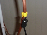
For this antenna construction, a RG59 coaxial cable with pre-fitted F-connectors was purchased. One end of the cable was cut off & stripped away to reveal the inner conductor & shield. The inner conductor is soldered to one ”leg’ of the loop antenna; the shield of the cable to the other ‘leg’.

The other end (F-connector) was connected to the masthead amplifier. Weatherproofing the connection may be necessary if the antenna will be used on a permanent basis outside.

Feedline input to FM loop antenna with ferrite choke © 2014 FM DXing

Feedline input to FM loop antenna with ferrite choke © 2014 FM DXing

Add-ons: Optional steps that may aid in optimizing the connection can be found in the Impedance Matching section, below.

The possibilities are limitless!

To receive long distance FM reception on the dual band Sangean WR-2 RDS receiver, enthusiast 1963DX constructed a quad FM loop antenna. That loop was optimized for about 109 MHz using copper wire on a wooden frame. Watch the video. Engineer Mike Thompson offers another version. About a decade ago, colleague John Faulkner G1VVP compiled a quarter wavelength version of the FM loop for the Skywaves club website. That design is made using coaxial cable. The original graphics have been mirrored at the Most Useful Information Ever.

Completed FM loop on the lawn © 2014 FM DXing

Completed FM loop on the lawn © 2014 FM DXing


Initial testing

The FM loop is a directional antenna which exhibits gain. Performance is simple yet effective.

When placed inside the house during winter, the antenna will enable reception of the following permanent signals:

  • 80 kW stations to 230 km / 143 mi;
  • 10 kW stations to 221 km / 137 mi &
  • 200 watt translators to 104 km / 65 mi.

Ideally for optimal performance, the antenna would obviously be placed outside. Metal objects inside for example, may cause interactions or obstructions. Outside, this antenna yields:

  • 100 kW stations to 328 km / 204 mi &
  • 3 kW stations to 286 km / 178 mi.

In the field, the FM loop antenna has performed extremely well. To date, the most distant evening spring-time tropospheric scatter reception occurred out to 578 km / 359 mi on an apartment balcony. Detailed field performance and photography may be found at the continually-updated Have Loop, Will Travel entry.

When the antenna is connected to a sensitive car radio or component tuner, the FM loop typically outperforms a Silabs’-based portable FM receiver with the supplied telescoping antenna. Much like a dipole, the FM loop antenna also offers good performance if connected to a portable receiver.

To be fair, crude testing under flat conditions may only offer support to assertions made about potential antenna performance! Objective measurements tend to be more reliable. These characteristics are discussed in the final section, below.


Gain

The quad loop exhibits a maximum of 1.14 decibels gain relative to a dipole (in other words, a 3.27 dBi gain) according to W8JI.

The 2005 edition of the ARRL handbook (reliant on NEC based antenna modelling data) specifies the maximum gain of a full wavelength loop to be 1.35 decibels relative to a dipole (these units are known as dBd).

For modelling comparisons between circular & square VHF loops of different dimensions, please refer to Holl_ands simulations.

What about the performance for this specific loop project? Well, modelling using MMANA-GAL Basic software suggested that maximum gain within the FM band for this loop may be as high as 1.44 dBd. Optimal SWR occurred above 105 MHz.

Comparisons to other domestic antennas

The FM loop may be ideal for long distance FM enthusiasts or listeners with a single fixed external antenna, such as a wideband television antenna.

Completed FM loop on the lawn © 2014 FM DXing

Completed FM loop on the lawn © 2014 FM DXing

A contemporary rooftop-mounted log yagi television antenna (for US channels 6-12 & UHF) will typically exhibit a maximum gain of 1 dBd for reception at the top of the FM band & a loss for stations below 95 MHz. The loop is likely to outperform such an antenna, even on a small mast 1.7 m (5.6 ft) above ground.

The smallest & most inexpensive rooftop FM yagi antenna (3-el FM yagi) will typically exhibit a maximum gain of between 4-5 dBd. For those yagi owners, a secondary antenna such as a loop may be useful where neighbouring electrical interference is affecting the rooftop antenna, the rooftop antenna is fixed in one direction (resulting in only weak signals audible ‘off-the-side’ of the antenna) or for testing purposes in conjunction with the main antenna.

These figures are provided in good faith, based on calculations performed in antenna modelling software & antenna manufacturer data.

Polarization

As the feedline input is entering at the side, this FM loop antenna is vertically polarized. This is one of several configurations to consider.

Impedance matching

Holl_Ands modelled 82-86 MHz & high VHF band circular loops. The modelling suggests impedance varied enormously with frequency.

Various sources suggest that full wavelength loops may exhibit a typical impedance of roughly 102 – 115 ohms. In chapter four of his book, electrical engineer Walton C. Gibson suggests a circular loop exhibits an impedance of 140 ohms at resonance. This impedance is about half that of the folded dipole.

Completed FM loop on the lawn © 2014 FM DXing

Completed FM loop on the lawn © 2014 FM DXing

Use of this antenna with standard 75 ohm feedline may cause a potential impedance mismatch. Mismatch loss may arise, where signal is reflected back to the antenna.

It could be argued that the impedance mismatch between (say) 140 ohms and 75 ohms has a negligible effect on ultimate received signal strength. Therefore, inserting a 1:1 current balun ‘home brewed’ from coaxial cable or ferrite suppression chokes represent two optional steps to consider. (Please refer to Brian’s website below). After these chokes have been inserted, a masthead amplifier may help compensate for potential mismatch loss.

Dimensions

The single dipole equivalent to this loop (with the same element diameter) is roughly 1.4 metres long, if measured tip to tip. A folded dipole requires slightly longer dimensions, typically 2%. Typically, the larger the tubing diameter, the greater is the potential bandwidth of an antenna. Element thickness is an important characteristic.

1/2 inch (12.7 mm) copper annealed coil was used to construct this loop antenna simply because the outlay was $10 cheaper than the same length of 3/4 inch (19.05 mm) coil! There were at least eight copper tubing diameters readily available to buy.

The following diameters of copper tubing are frequently used to construct circular loop antennas on the six metre, FM & high VHF broadcast bands:

  • 3/8 inch (13.06 mm);
  • 1/2 inch (12.7 mm) tubing or
  • 1/4 inch (6.35 mm).

A final word: Mounting

As pictured, a satellite tripod is used to secure this FM loop antenna. These are priced between $50 – $70. A more inexpensive garden sprinkler tripod ($30) also works. Alternatively, mounting the FM loop inside on a large window may also be feasible. The weight of the copper tubing (dependent on the chosen thickness) will need to be secured to the window, as to ensure the antenna does not fall over!


Reference books

Antenna Basics by Christof Rohner et. al.

Antenna Design for Mobile Devices by Zhijun Zhang

Method of Moments in Electromagnetics by Walton C. Gibson

Radio Antenna Engineering by Edmund A. Laport


Reference websites

Antenna-Theory.com

Brian, K6STI

Frits, PAØFRI

Simone, IW5EDI

‘Yukon John’, KL7JR


Antenna software

John, VK5DJ

MMANA-GAL


Lecture notes & Powerpoint slides

A practical approach to HF-VHF antennas, plus antenna myths & mysteries by Terry Graves, K7FE

Computer antenna modelling simplified by Larry J. LeBlanc, KE5KJD

Loop Antenna characteristics by Pat Donohoe PhD


This entry was last updated during December 2014.

Salvage for salvation: budget FM radios in a post apocalyptic world

Historical records suggest that this electronics shoot out was conducted during a chilly, overcast winter morning. It was as bleak and lifeless as a post nuclear apocalyptic scene akin to the Terminator. It was speculated that a small gang of elitists running the incumbent government had somehow vaporized the masses of decent folk with their relentless, soul-destroying dogma and double talk.

Apocalypse  © 2008 Michael Lehenbauer

Apocalypse © 2008 Michael Lehenbauer

All was not lost. The ‘suits’ had left some populist toys to play with. The few broken souls that remained in the city post apocalypse grabbed their toy radios. These were amongst their only remaining electronic devices. Could these rescue them from sheer desperation?

Graffiti: Greed is deadly © 2007 Bart Everson

Graffiti: Greed is deadly © 2007 Bart Everson

It was rumoured that the internet – the old world hub of information transfer had been sold by the self-interested elite to the highest bidder. Restricted to the highest echelons, few mortals possessed the social connections to enable access to the electronic network that once had the capacity to empower the disenfranchised and wealthy alike. Now, social mobility was virtually impossible.

No weather indicators to were available. Accordingly, tropospheric enhancement to FM signals could be tracked on-line. Synoptic charts were not available. The FM band that did exist was as boring as hell, filled only with those routine permanent FM signals. DX enthusiasts (those that monitored distant radio signals) were a forgotten breed. In this new world order, survival was the only concern. Hobbies became solely the domain of the wealthy.

Wise words, In Greed We Trust © 2014 Ed Suominen

Wise words, In Greed We Trust © 2014 Ed Suominen

But the nightmare was only beginning. It is clear that the poor mortals (those determined few that were left) struggled on with their souls intact. As pointless as it seemed to be in that environment, their capacity to test and experiment would endure.

It is now known that amongst the ruins of their old municipalities they conducted many seemingly fruitless tests. What follows is one such test; a shoot-out. Where possible, the original source material is quoted from…

Populist’s dream radio shoot out

The simpletons focused on two cheap ‘bastards’ with a ‘fearsome’ reputation to uphold. When the economy still functioned, these radios were purchased at retailers like Junk World. It was said that the two machines the simpletons had chosen empowered them, coupled with their tenacity to ‘fight it out until the death’!

Junkworld © 2010 Danny Choo

Junkworld © 2010 Danny Choo

A populist’s dream, the contenders consisted of the ADS Tech RDX-155 Instant Radio USB device versus discounter Aldi’s entry level Bauhn ADS-215 dual band portable radio…

Bauhn Digital Receiver Geeks.com ADS Tech RDX-155 Instant Radio marketing photographs

Testers’ performance data

Table 1: Sensitivity equivalence illustrating selected moderate-weak stations

FREQUENCY  DISTANCE  POWER INSTANT RADIO BAUHN
88.5 53mi 26 kW YES YES
89.3 48mi 25 kW YES YES
90.5 43mi 200 watts YES YES
91.1 35mi 10 kW YES, RDS YES,  RDS
91.7 53mi 26 kW YES YES
92.1 43mi 5 kW YES YES
92.5 48mi 25 kW YES YES
94.1 48mi 25 kW YES YES
94.5 88mi 100 kW YES YES
94.9 26mi 50 kW YES YES
95.3 88mi 100 kW YES YES
95.7 53mi 26 kW YES YES
96.9 88mi 100 kW YES YES
97.7 53mi 26 kW YES YES
98.5 88mi 100 kW YES YES
102.9 25mi 48 kW YES YES
104.1 65mi 1 kW YES YES
105.7 48mi 10 kW YES YES
107.3 48mi 10 kW YES YES


Table 2: Marginal signals illustrating reception differences between the two budget receivers

FREQUENCY DISTANCE POWER INSTANT RADIO BAUHN
90.9 25 mi 48 kW 2 / 2 0 / 2 – ACI
95.9 40 mi 1.6 kW 0 / 2 – RFI 2 / 2
96.1 88 mi 100 kW 0 / 2 – RFI 1 / 2
99.4 48 mi 2 kW 2 / 2 1 / 2
100.6 48 mi 2 kW 2 / 2 1 / 2

Salvaging suitable antenna connections

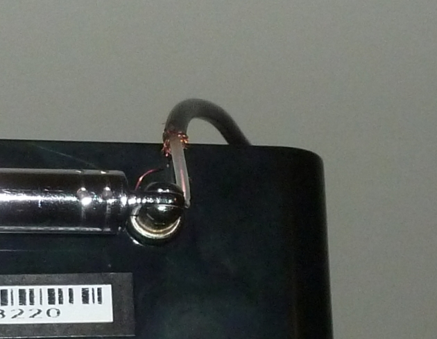
The Bauhn ADS-215 radio was also connected to the rooftop antenna via a 1 m / 3.28 ft high grade RG59 cable. To connect the antenna internally would void the warranty. Moreover, it is difficult to achieve this as the plastic case must be plied open, since there are no screws!
External antenna connection on Bauhn ADS-215 © 2014 FM DXing

External antenna connection on Bauhn ADS-215 © 2014 FM DXing

On the unit, cable was connected to the DC adapter ground [not pictured] and the collapsed telescopic antenna. The radio was powered using the supplied 5 volt DC adapter.

Optionally, if cutting coaxial cables is unpleasant, connection can be easily made via a 30 cm / 1 ft twin-lead wire then a 4:1 matching transformer. To be perfectly honest, transformers do pose some insertion loss as part of any antenna system. Surprisingly, no difference in signal strength of weak stations was detected between connection methods.

RDX-155 Instant Radio was connected to the rooftop antenna via a 1 m / 3.28 ft high grade RG59 cable. This cable also may cause some loss of signal and be susceptible to interference from the USB device. Sure, RG6 quad shield cable is better, but in practice the centre conductor is too thick to reliably connect to a pint- sized USB PCB. The laptop was powered using a battery.

It is speculated that access to laptop computers was not a trivial matter. Computers were  rare and prized possessions in post apocalyptic life. Because access to the internet was predominantly impossible, these computers were useful for processing needs only and recording data.

Fortunately, Instant Radio posed few Central Processing Unit (CPU) demands and looks to have functioned remarkably well on these old machines. How the simpletons ever charged that battery without a reliable mains power grid (they could not afford the onerous electricity bills) remains a mystery…

Post apocalyptic broadcasting

Records show that only an FM test was possible. But it was noted (amongst the word processing files found) that with the Bauhn dual band radio, full strength DAB+ reception (174 – 240 MHz) was available with the rooftop antenna. Photos were found of the graphical bars of the signal meter. Its Gyro Signal 1128 chip permitted satisfactory dual band reception at this time. (We don’t know the manufacturer’s objective sensitivity measurements for this module, but an Adobe Reader document with the FM performance of their 2005 module can be found via the end links). Retailing at $30, the Bauhn ADS-215 radio was likely to be an affordable choice for those with limited fiscal capabilities.

No contemporary music was being released or recorded. The broadcasts on the DAB+ multiplexes in these times included songs performed by old school cover bands such as Il Divo & Celtic Thunder. Music that was deemed to be fodder for the oppressed was reportedly banned for broadcast. For example, ‘aggressive’ releases by Neil Young, Metallica, the Dixie Chicks & John Butler Trio were illegal to broadcast, even if the recordings had been retained by some members of the elite. It has been suggested that the themes in these artists’ works may have been incompatible with the extremist ideology of the ruling elite…

Bauhn ADS-215 post Apocalypse © 2014 FM DXing

Bauhn ADS-215 post Apocalypse © 2014 FM DXing

Luxurious RDS performance suggested

Seven signals in the [above] table are known to provide digital Radio Data System (RDS) data. Six of these signals were too weak to decode. Only one quieting-level signal was included in the test, a broadcast on 91.1 MHz. On this channel, RDS data decoded easily on both units. RDX-155 Instant Radio offers faster decoding than the Bauhn ADS-215 radio. The Programme Type data (alone) decoded reasonably quickly on the Bauhn radio, but Instant Radio has a clear edge.

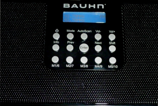
PI code mode on Bauhn ADS-215 © 2014 FM DXing

PI code mode on Bauhn ADS-215 © 2014 FM DXing

Close up, PI code mode on Bauhn ADS-215 © 2014 FM DXing

Close up, PI code mode on Bauhn ADS-215 © 2014 FM DXing

The Bauhn ADS-215 radio will display unique station identification codes called PI codes as part of the RDS digital data. This feature may offer potential value for DXing.

Post war, it is known that the elite took control of electronics and computing power. Whilst the elite played real life games on the stock market, the mortals continued their desperate simple tests. Trivial? Indeed. But it is all they had. They continue…

Riding out the Apocalypse © 2011 David Blackwell

Riding out the Apocalypse © 2011 David Blackwell

Differences testers observed

Where differences were noted between receivers on any particular frequency, the test was conducted twice. Between 95.9 – 96.1 MHz, no signal was heard due to heavy interference obstructing potential reception on RDX-155 Instant Radio. The interference was caused by a spurious signal.

This annoying side effect is a widely reported issue with the device that cannot be readily remedied by ferrite suppression chokes. It will be offset by a masthead amplifier, of course. Conversely, no spurious signals were observed on the Bauhn ADS-215.

Bauhn ADS-215 post Apocalypse © 2014 FM DXing

Bauhn ADS-215 post Apocalypse © 2014 FM DXing

On 99.4 MHz & 100.6 MHz, only weak signals were detected. Nonetheless,  RDX-155 Instant Radio appeared to outperform its rival in terms of sensitivity. On 90.9 MHz, no signal was detectable due to adjacent channel interference obstructing potential reception of the broadcast on the Bauhn radio. Again, this suggests selectivity out-performance by the Silicon Laboratories’ (Silabs) integrated circuit inside in the Instant Radio.

It is thought that back in the ‘olden days’, Silabs produced radio electronics that every man, woman or android could afford. Although Silabs mainly produced chips for portable standalone radios at this time, the RDX-155 Instant Radio represented somewhat of an oddity; a discontinued $17 computer-based tuner in a tiny USB enclosure.

Intermodulation dynamic range was tested on empty or very weak channels. Strong signal immunity is extremely important for FM reception applications and arguably a more important characteristic for any FM tuner than any simplistic sensitivity measurement or test. It is pleasing to report that no ‘ghost signals’ were detected on either receiver, despite the congested band. Accordingly, a high quality signal amplifier (ideally a masthead amplifier, positioned at the antenna) may increase sensitivity without compromising performance.

Instant FM Radio post Apocalypse © 2011 Synx 508

Instant FM Radio post Apocalypse © 2011 Synx 508

Simpletons’ summarized observations

The test (as collated in the table) suggests that potential differences in sensitivity, (if any exist) are likely to be negligible between ADS Technologies’ RDX-155 Instant Radio & Aldi’s Bauhn ADS-215. Weaker signals, such as the 90.5 MHz translator are not readily detected in flat winter conditions. The performance of Instant Radio was superior on three stations (probably due to better sensitivity and selectivity) but internally generated interference tended to offset any gains.

These findings suggest that the simpletons were confident both units would provide satisfactory FM reception for the modest outlay they originally paid at retailers like Junk World.

The broken souls understood a masthead amplifier could be used with these inexpensive receivers to improve performance when coupled with an external antenna.

Junk electronics © 2007 Marco Bernardini

Junk electronics © 2007 Marco Bernardini

It was beyond the means of most, but they found some antenna pre-amplifiers on the streets; regrettably their beloved streets had become so littered with redundant electronics their suburbs resembled a rubbish dump. These cheap radios gave the broken souls hope for the future. Finally their story of hope can now be shared for the benefit of future generations.

Society’s future is unwritten. Government policy or individual action that promotes greed, entrenches class divisions & exacerbates poverty is the real ‘junk’ of the world!
Non-fiction reference material!

Extensive test of Instant Radio RDX-155

Boxing kangaroo test of Bauhn ADS-215

Gyrosignal 1122 FM/DAB receiver module specifications

Masthead amplifiers potentially benefit weak FM signals

Role of RDS data in long distance FM reception

Quest for silence: Quiet SATA notebook hard drives

When using a notebook computer for audio applications, unfortunately it isn’t simply a matter of buying the most reliable big hard drive. Using a notebook with either a Software Defined Radio (SDR) or as a playback device when recording from external components (such as a tuner) means noise matters. Hard drives produce noise which affects concentration in critical listening applications where the signal to noise ratios are critical… especially with ‘compromised audio’, which is often characteristic of weak radio signals or old recordings.

Noise Factory © 2010 Alexander Marco

Noise Factory © 2010 Alexander Marco

Hard drive evolution

The differences in hard drive technology are often quite obvious. Even within the last 15 years, the average person can readily compare old 3.5″ IDE hard drives to modern ones and notice the mammoth difference in audible noise, even with the software inactive (idle mode). More recently, there is often a noticeable difference between SATA drives with their increasingly rare IDE counterparts.

A decade ago, New York inventor Neil Singer suggested:

The level of noise in a disk drive is due to vibrations at particular frequencies, such as 6.6 KHz, 6.0 KHz, 5.0 KHz, 4.2 KHz, and 1.3 KHz. On the other hand, mechanical vibrations, which reduce seek time, result from vibrations at different frequencies, such as 3.3 KHz.

Today, Solid State Drives (SSDs) are generally considered to be ‘silent’ storage technologies. Problem solved, right? Perhaps, provided one has inordinate wealth! The cost associated with buying a huge SSD means these aren’t necessarily cost effective choices for radio DX applications where uncompressed audio demands may be onerous; a 6.14 MHz ‘spectrum chunk’ may consume as much as 120 GB of data per hour.

Research aids

For specific needs, the Silent PC Review (SPCR) test articles and forums are an invaluable, simple to understand resource in the quest for finding quiet hard drives, whether external, internal, desktop or laptop variants. Further, hard drive manufacturer Western Digital (whose part reliability is top notch) provides acoustic specifications in dBA on their website. Other manufacturers such as Hitachi & Seagate may also provide this data.

Much of this information (sadly, including this article!!!) becomes redundant quickly after publication. Before committing to recommended drives, it is prudent to check with manufacturers that there are not better performers that may have just been released.

Eventually the cost of SSD technology may become so affordable that it is foreseeable that there will be negligible demand for acoustic tests on the subject matter of this article. The reality is that SATA drives are older, less efficient performing drives but for now, remain perfectly appropriate choices. Drew Riley of Tom’s Hardware portal suggests:

Even though SSDs only account for 10% of the total market, growth over the next few years is expected to be explosive.

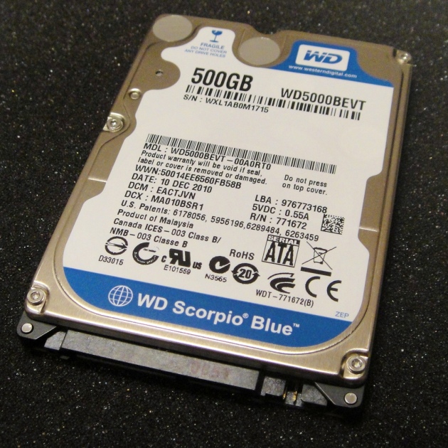
WD 2.5" SATA drive © 2011 Matt Kieffer

WD 2.5″ SATA drive © 2011 Matt Kieffer

Needs analysis

This blogger wanted to buy a 2 TB hard drive for a new notebook which is already furnished with a single 1TB (5400 rpm) drive, which incorporates a second bay for a secondary hard drive. SSD drives were not considered due to cost; a typical 1 TB drive costs over $600 and over half that for 0.5 TB. Although fast, external USB 3.0 drives were also not considered due to already congested desk space. Hell, there’s enough crap lying around!

Whilst affordable, those desirable 2TB SATA drives are typically considerably noisier than their smaller capacity counterparts. So significant was the increase in noise (based on the dBA specifications) this prompted a reassessment as to whether bigger was necessarily critical for the particular SDR application. If the noise is problematic, even if there are two internal bays, it’s not so easy to switch internal drives off unlike an external drive. Therefore it’s probably worthwhile to research the most appropriate internal drive, rather than be forced to tolerate a noisy drive by judicious use of headphones or a proportionate increase in playback volume!

Three top candidates

Priced from $45 including domestic shipping:
Western Digital Scorpio Blue 0.5 TB with SATA 6 Gb/s interface (WD5000LPVX)
Manufacturer specifications (dBA): idle 17, average seek 22.

Priced from $62 including international shipping:
Western Digital Scorpio Blue 0.5 TB with SATA 3 Gb/s interface (WD5000LPVT)
Manufacturer specifications (dBA): idle 17, average seek 22.
This drive won the Editor’s Choice at SPCR.

Priced from $125 including domestic shipping:
Western Digital Blue 1 TB (WD10SPCX)
Manufacturer specifications (dBA): idle 20, average seek 21.

One of the quietest 0.5 GB drives, the WD5000MPCK (idle: 15, seek: 17) was unfortunately no longer readily available. Obviously, when reading the dBA specification, lower is quieter. To convert between acoustic units please use the calculator below. It seems that manufacturer Seagate for example, cites noise measurements using bel units rather than dBA.


Further reading

Acoustic unit calculator

Advanced PC silencing

Benefits of Solid State Drives

Eight different 2TB hard drives, with dBA measurements

Home Studio construction

Silent Windows laptops?

Things you can do to have older laptops quiet again

Top 5 external A/V-rated drives for audio recording

World’s quietest (desktop) computer

Dusting off old tech: Setting a daily unattended FM recording

Listeners may have a need for daily recordings of certain desirable FM broadcasts such as music programmes or sporting event calls. The use of online streaming to time shift broadcasts may offer an easy solution, but problems still exist:

  • Potential loss of audio quality, due to artifacts (audio distortion) associated with low bitrate streams
  • Anxiety over burning through the monthly internet data allowance, or the
  • Ever-increasing prevalence of ‘geoblocking’ due to music licensing restrictions.

Perhaps the radio recording app doesn’t permit recording of distant FM stations on the smart phone?

Radio Concierto "Concierto Enfoque" © 2005 Leo Prieto

Radio Concierto “Concierto Enfoque” © 2005 Leo Prieto

Enthusiasts who pursue long distance FM reception may need to monitor a specific vacant frequency every day to check the presence of signals propagated via Sporadic E or tropospheric ducting, especially during summer. This technique is often referred to as recording DX audio.

The ultimate solution to their specialist needs is to purchase a Software Defined Radio (SDR). An SDR probably represents the most efficient way to participate in long distance FM reception, without the often exhausting and time consuming burden of ‘live listening’ when propagation conditions happen to be favourable.

But many FM enthusiasts cannot justify the outlay of approximately $1,400 on a Micro Telecom Perseus Software Defined Receiver (SDR) with an FMplus down converter. And when one takes into account the minimum hardware requirements, their fellow Italian counterparts including the Elad FDM-S1/PDC-FM combination or FDM-S2 are not much cheaper either.

Recording FM broadcasts… on the smell of an oily rag!

By using simple but effective old technology, setting a daily unattended FM recording remains easily within reach for everybody.

There are likely to be numerous ways of achieving this, using an old computer. To implement this blogger’s preferred method, the following equipment is required:

  • Microsoft Windows XP operating system (or above)
  • Leadtek Winfast TV2000XP FM tuner card (or equivalent)
  • Rooftop FM/VHF/UHF antenna connection with ferrite chokes clipped onto cables.

The following equipment (as used in the final step) is desirable:

  • Desktop computer with a Bios that supports Auto Switch On.

The Leadtek Winfast TV2000XP is a sensitive FM tuner card which is readily available for $5 – $15 on the second hand market. The card has software available for Windows 7, Vista, XP and 2000. For simplicity, XP will be used in this guide since the TV2000XP software was optimized for this operating system.

Flexibility

Although the three mandatory steps below might initially look daunting, the beauty of this technique is that performing these steps is generally only required once. Furthermore, the technique is not restricted to unattended software recording tasks. To fully automate another task (such as a virus & malware scan) replace this task into steps one and two.

Old desktop computers © 2009 Brian Landis

Old desktop computers © 2009 Brian Landis

Virtually any old desktop PC (manufactured after 2002) should be a candidate for such ‘old school’ simplicity. It’s perhaps an opportune time to dust off disused Windows XP computers which may not be cost effectively upgraded to Windows 8 operating system after Microsoft’s cessation of support.

FIRST STEP – Setup Winfast FM in Windows Startup

A
Click on START
Search hard drive for WFFM.exe
Note which directory this application file resides in, for example: E:\Program Files\WinFast

B
Click on START
Search hard drive for Startup
In the list of results, there will be Startup next to a folder named something like:
E:\Documents and Settings\joebloggs\Start Menu\Programs
Click on Startup and leave window open.

C
Click on START
Click on RUN
Type in E:\Program Files\WinFast (or whatever directory it is, obtained from step A)
Locate WFFM.exe
Right click CREATE SHORTCUT
Drag the newly created shortcut into the Startup folder left open from step B.

Restart the computer. Please ensure Winfast FM starts up automatically.

Hint: Tuber Guru Fuel has made a video if the author’s approach (above) looks too boring to even contemplate!

SECOND STEP – Setup the timer in Winfast FM

The desired channel, number of hours and recording quality must be chosen in this step. Specific days may be chosen. For example, every Monday between 7-10 pm, Monday night football may be recorded.

WinFast Daily Recording Schedule © 2014 FM DXing

WinFast Daily Recording Schedule © 2014 FM DXing

Obviously, please ensure that the chosen frequencies (radio stations or vacant channels) to be recorded have been added in. To do this, click on CONFIGURATION button in Winfast FM and navigate to the CHANNEL LIST on the top centre.

Ensure antenna is connected and enter the schedule as follows:

Click on CONFIGURATION button in Winfast FM
Click on SCHEDULE button on the top right

Click on ADD at the bottom left
Under ACTION select RADIO RECORD
Under CHANNEL pick the frequency
Under FORMAT choose a PCM or a compressed format if disk space is tight

Under DAILY tick the applicable days
Under FROM select the Start Time
Under TO select the End Time

Double check details and select OK. Please take note of End Time and Start Time chosen.

WinFast Daily Recording Schedule © 2014 FM DXing

WinFast Daily Recording Schedule © 2014 FM DXing

For additional information on setting an FM recording schedule please click on the ? button within the software.

Ideally run a test scheduled recording consisting of a few minutes duration. Once complete, please check the contents of the recorded file to ensure it contains the desired broadcast.

THIRD STEP – Setup shutdown in Windows Scheduled Tasks

The aim is to ensure the computer switches off after recording. Blogger the Spinning Donut has a step-by-step guide and video for guidance.

Windows Daily Shutdown Schedule © 2014 FM DXing

Windows Daily Shutdown Schedule © 2014 FM DXing

Ideally run a test scheduled shutdown for a few minutes into the future. Once the system is shut off, please restart it.

When setting the time for daily shutdown, please use the End Time specified in step two, but add an additional 5 minutes. For example, if the End Time of the radio recording in Winfast FM Schedule is 11:30 please ensure the Windows shutdown is set for 11:35.

This allowance will ensure that the end of the recording is written to the hard drive, meaning that a valid sound file will consequently be playable with all audio software.

Hint: Third party software that will schedule a daily Windows shut down may be used as an alternative.

FOURTH STEP – Setup daily startup in BIOS 

The aim is to ensure the computer switches on before recording, an optional but desirable process.

A PC World Wiki contains a step-by-step guide to Wake System settings with screen shots.

When performing this final (and the simplest) step, please take note of the Time and Date configured in the Bios. Ensure that the WAKE UP TIME / RTC ALARM TIME selected in the Bios is before the Start Time chosen in Step two. For example, if one sets the system to wake 10 minutes prior to the recording Start Time set in the FM recording scheduler, this ‘factors-in’ the starting up delay of Windows.

These screen shots show the settings to configure the computer to wake at 0730 hours every morning. Each Bios may be slightly different, if in doubt please refer to the printed instructions supplied with the motherboard.

BIOS Daily Wakeup Schedule © 2014 FM DXing

BIOS Daily Wakeup Schedule © 2014 FM DXing

If Daily is not listed in the Bios facility, ensure the WAKE UP DATE / RTC ALARM DATE is to be set to 0 for daily system wakes. Whilst it is very simple, as always a trial run is recommended to ensure familiarity with the date and time format. Finally, don’t forget to save WAKE SYSTEM / RTC ALARM settings to CMOS when exiting the Bios facility! With this Bios, F10 does the trick.

BIOS Daily Wakeup Schedule © 2014 FM DXing

BIOS Daily Wakeup Schedule © 2014 FM DXing

Hint: Obviously when there is no longer any ongoing requirement to automatically start the PC for daily recording etc. it may be convenient to DISABLE the above WAKE SYSTEM / RTC ALARM settings!

Practical considerations

Some computer Bios facilities may not offer a Wake or Alarm System setting where the computer will switch on without intervention, as described in step four. Nonetheless, under those circumstances one can still follow the instructions to schedule recordings to commence and then shutdown, as listed in steps one to three above. Of course, one must be home to physically start the computer or already be using the computer for other tasks. For this reason, the provision for WAKE SYSTEM FROM S5 or similar Auto On facility in the Bios is considered a prerequisite for implementing a fully unattended recording system as proposed in this guide.

Windows Password & Login Settings © 2014 FM DXing

Windows Password & Login Settings © 2014 FM DXing

Step four will not work if the User Accounts in Windows XP (above) are set to require users to enter passwords & / or press Control-Alt-Delete as a security measure on Windows startup to operate software. These logins require user intervention, which is incompatible with the goal of unattended recording. These Windows logins are easily disabled (reference video). Moreover, password protected logins are overkill for old desktop computers that are not connected to the internet, but dedicated to the task of recording!

Alternative Power Management features such as reduced power Hiberation or Standy By modes are beyond the scope of this guide. The method above allows for maximum power saving. Since the computer system is only operational when required, there is also no potentially annoying fan and hard drive mechanism noise; older desktops can indeed be noisy.

Once it has been established that settings are configured properly during a test run, daily recording settings can be implemented. Enjoy the automation and the maintenance of old tech!

Testing: the method has been tested numerous times with several disused single-core CPU (3 GHz) computers using ASRock K7VT6 & Asus P5GZ-MX motherboards. These of course, feature a Bios that supports Auto Switch On. 

Revisiting the Realistic PRO-2006

Around 1990, Tandy Corporation introduced the Realistic PRO-2006 programmable scanner. It was manufactured for Tandy by General Research of Electronics, Inc. (GRE) in Japan. It is also known in Europe as the Commtel COM-205 or Handic 0080 (below), according to Javiation.

Handic 0080 aka PRO-2006 © 2011 Wanderlinse

This triple conversion receiver offers microprocessor-controlled VHF, UHF and FM reception. A rooftop antenna or whip (supplied) is connected via the BNC antenna connector. The scanner sold for a retail price of $400 in the United States.

Realistic PRO-2006 © 2014 FM DXing at WordPress

There are plenty of modifications that can be undertaken for this scanner. These include the ability to tap the discriminator output or the 455 kHz third Intermediate Frequency (IF) signal for SSB demodulation. An HF receiver or modern outboard conversion hardware (such as RadiØKit-2 in combination with open source Dream software) is required to demodulate the SSB from the IF signal.

Being relatively lightweight, the PRO-2006 offers genuine potential during field trips at summits. The scanner is easily operated using an inexpensive, lightweight and rechargeable Sealed Lead Acid (SLA) battery.  A battery with a capacity of nine Amp hours (Ah) is more than adequate for this scanner. A handheld MP3 recorder featuring line-in recording can be connected to Tape Output on the rear of the scanner to permit monophonic recording of reception, including FM broadcasts.

Realistic PRO-2006 supplied antenna © 2014 FM DXing at WordPress

FM broadcast band tuner module

The PRO-2006 incorporates two 280 kHz, two 455 kHz ceramic filters and a 48.5 MHz crystal filter. Wide FM mode is designed for analogue FM and TV audio only.

Realistic PRO-2006 tuner module, rear unit perspective © 2014 FM DXing at WordPress

The PRO-2006 has two 10.7 IF bandpass filters in the FM section (above). These are both marked 10.7A, suggesting a 280 kHz bandwidth. The part number is Murata SFE10.7MA5W-A. The bandwidth of these filters is too wide to discriminate FM stations spaced 100 kHz or 200 kHz apart on the contemporary congested FM band.

PRO-2006 partial schematic © 1990 Tandy Corporation

KA2243N (IC1)  is the IF amplifier/detector Integrated Circuit (IC). The first 280 kHz filter (CF1) leads directly to pin 1. The second 280 kHz filter (CF2) leads to pins 4 and 6. The HA12413 IC may be substituted for the KA2243N.

This tuner module incorporates the IF coils and the Quadrature/detector discriminator coil for both 48.5 MHz (T1, T2) and 10.7 MHz (T3, T4).

FM broadcast band performance

The nominal 30 decibel FM sensitivity ‘design specification’ for the PRO-2006 is 3 microvolts for frequencies from 25 – 520 MHz. The FM broadcast band falls into this segment.

Radios featuring a Si4734 digital AM/FM radio receiver IC, such as those manufactured by Tecsun, offer approximately equal sensitivity as the PRO-2006 scanner in Wide FM mode. It is impossible to make entirely accurate comparisons between the Silabs’ Digital Signal Processing (DSP) based receivers and conventional tuners, since the company use differing units and test conditions to measure sensitivity. However, the nominal 30 decibel FM sensitivity ‘design specification’ (below) from Tecsun, applicable for radios such as the PL-300WT & PL-606) is better than 3 microvolts for frequencies from 64 – 108MHz.

Tecsun specifications © 2014 FM DXing at WordPress

How to access the tuner module

Unscrew the two, top positioned screws on the rear of the scanner. Remove the top plastic cover top to expose the ‘linear printed circuit board’, PC1. Remove the metal cover of the tuner module (below), which is located second from the right.

PRO-2006 interior modules © 1990 Tandy Corporation

Replacing wide 280 kHz filters in the PRO-2006, PRO-2005, PRO-2004, PRO-2035 or PRO-2042 scanners is likely to be as simple as the modification to the Philips FM1216-based tuner module, used in television tuners such as the Winfast TV2000XP. An excellent resource for this modification is GBPPR Projects.

Realistic PRO-2006 frequency display © 2014 FM DXing at WordPress

Mating the PRO-2006 with a Software Defined Radio (SDR)

After filter replacement, tapping the 10.7 MHz IF (both mods are described at GBPPR Projects) may enable the 10.7 MHz output from the scanner to be manipulated with DSP functionality in an SDR. Unfortunately, readers wishing to do so are ‘on their own’ because the writer does not own a compatible SDR (such as the SDR-IQ). It may be instructive to watch the video Gough Lui made. He taps the 10.7 MHz IF of the PRO-2021 scanner into the Winradio Excalibur SDR. Peter employs the same principle in his video.

A more inexpensive alternative may be to use a High frequency (HF) upconverter in combination with a cheap RTL-SDR receiver. Such upconverters are available for under $50. Unlike the cheap RTL-SDR receiver itself, an upconverter will tune into the 10.7 MHz output frequency from the scanner. There are side effects in this approach, which potentially include a 10 decibel loss and the limiting dynamic range of the RTL-SDR receivers.

Pairing the scanner with an SDR offers hobbyists the opportunity to extract the maximum potential audio quality out of FM broadcasts or International Radio and Television Organisation (OIRT) broadcasts on 66-74 MHz still on-air in Eastern Europe.

Creative Commons license - Click here for details

PRO-2006 photographs may be freely used for non-commercial activity, provided attribution is given. Should readers choose to use those photos elsewhere, please link back to this page or attribute this blog as the copyright holder. Please click on the photos for higher resolution shots (2048 x 1536 pixels).

Eighties Retro Radio

Rewind time back to 1988 and an ‘el cheapo’ FM stereo tuner kit looked like this! The three modules pictured below consisted of an:

  • FM tuner (steel shielded front end),
  • Intermediate Frequency/detector (IF) &
  • FM stereo decoder.

The three modules connect together with 28 inexpensive supporting components to comprise a fully functioning FM/AM tuner with a basic signal strength meter, LED stereo indicator & coaxial cable antenna input.

Tuner module © 2014 FM DXing at WordPress

Module for IF & Detector © 2014 FM DXing at WordPress

Module for Stereo Decoder © 2014 FM DXing at WordPress

The tuner featured analogue tuning with switchable Automatic Frequency Control (AFC) feature. AFC is rarely mentioned these days. In a nutshell, AFC circuitry automatically locks to the tuned frequency so as to facilitate ‘drift free’ reception of the desired FM broadcast; automatic correction is applied when the dial is ‘off-tuned’. In a congested FM band, the function is best switched off, otherwise that weak signal might be hard to find.

Contents of Electronics Australia magazine © 1988 Federal PublishingCover of Electronics Australia magazine © 1988 Federal Publishing

The above tuner was featured as a Do It Yourself (DIY) kit in the now defunct Electronics Australia magazine (above) from April 1988. Hand written & printed schematic diagrams and modules (above) were found in buried in an old set of drawers.

The schematics for each module appear below:

FM tuner schematic © 2014 FM DXing at WordPress

FM IF & detector schematic © 2014 FM DXing at WordPress

Stereo decoder schematic © 2014 FM DXing at WordPress

Further reading

1974 MPX-stereo decoder with TCA290A

TCA420a datasheet

AFC Definition

AFC Explained

What is AFC?

Why choose plain FM over FM AFC?

FM USB Tuner Shootout: PC Ear vs Instant Radio (ADS Tech RDX-155)

Welcome to another radio shootout, Boxing Kangaroo edition! These shootouts feature ‘dirt cheap’ radios and are intended to appeal to a variety of different potential audiences, including terrestrial FM radio listeners and hobbyists interested in elementary electronics or FM reception capabilities.

Boxing Kangaroos in the zoo © 2011 Scott Calleja

Digital Signal Processing on the cheap?

At the time of writing, the cheapest Chinese portable FM radio currently available incorporating Silicon Labs’ (Silabs) Digital Signal Processing (DSP) costs about $49 including delivery. This model is the Tecsun PL-606. For those with a laptop and access to a directional antenna, USB computer devices with the SI4700/01 integrated circuit (IC) are considerably more inexpensive, representing a cheap entry to Silabs DSP.

 Tecsun CR-1100 © 2013 James Case

 Tecsun PR-380 © 2013 James Case

The contenders: Two popular Silabs USB FM tuner

Instant FM Radio (Instant Radio) costs about $17 including delivery.

USB FM Radio Player © 2005 Silicon Laboratories

MP3car.com ADS Tech RDX-155 Instant Radio under Windows 7, Canberra Australia

Geeks.com ADS Tech RDX-155 Instant Radio marketing photographs

PC Ear FM Radio Player © 2014 FM DXing

PC Ear costs about $17 wholesale but is no longer readily available new.

PC Ear unboxed © 2014 FM DXing

Gunning for the best: PC Ear versus Instant Radio

A rudimentary inspection of the datasheets suggest the FM sensitivity measurements are equivalent for the Silabs ICs inside PC Ear and Instant Radio. To test this, a modest directional antenna was connected to the devices. Both devices were housed in a metal enclosure with two suppression chokes and operated with a Radio Frequency (RF) quiet laptop running from battery power.

Reception conditions were well below average with heavy, unrelenting rain. 15 stations were chosen for the test. Of these, 13 stations were detected with the minimum signal strength of 0, where signals are just audible above the noise floor. Because of the heavy rain, two of the usual weak signals were not audible during the test and accordingly, do not appear in the performance table.

Software

PC Ear does NOT support firmware upgrades using the Windows-based Silabs configuration software utility. Firmware updates to PC Ear can be done under Ubuntu/Linux, but the process may be complicated. The Silabs Radio DLL software appears to function, but audio issues were evident when tested briefly with PC Ear. According to the developers, it is supported.

The upgraded firmware was used with Instant Radio. The upgrade was performed per the ADS Configuration user guide instructions for Silabs Radio DLL, developed by Beezer, Guino and Pete.

Characteristic PC EAR  INSTANT RADIO
Tunable frequency range 76 – 90 MHz, 87.5 – 108 MHz 76 – 90 MHz, 87.5 – 108 MHz
Circuit board approximate size 1.3 x 0.6 inches 2.4 x 1.1 inches
Tuning steps 50 kHz 50 kHz
Radio Data System support No Yes
Software support USB Radio 2.0-3.0 (supplied), FM Signal Strength Analyzer 1.0.0.19, Silabs Radio DLL, Silabs configuration software utility. Instant Radio 1.0.0.11 (supplied), Silabs Radio DLL, FM Signal Strength Analyzer 1.0.0.19, Silabs configuration software utility.
Hardware version PC Ear 1.77 Silabs 1.7.15
Firmware upgradable No, Please refer to body of article Yes, ADS NoiseMod Primary.dec

The software support listed in the characteristics table (above) is NOT exhaustive. Please understand that the priority was to test reception performance.

Any frequency (or broadcast) can be easily recorded for hours ‘on schedule’ using third party Windows audio recording schedule software such as Fox Magic Audio Recorder (free) and High Criteria Total Recorder Professional ($36). The software supplied with the devices also offers recording ‘on demand’. ADS Tech Instant Radio software is especially recommended for this purpose, since it offers high resolution 96 kHz uncompressed recording capabilities.

Closeup of ADS Tech Instant FM Music PCB © 2014 FM DXing

Comparative performance

PC Ear is constructed on a double sided printed circuit board, whilst the Instant Radio device uses a much larger single sided board (above). Unsurprisingly, both designs feature surface mount components.

RADIO STATION FREQUENCY (MHz) PC EAR MAXIMUM SIGNAL STRENGTH (BARS) INSTANT RADIO MAXIMUM SIGNAL STRENGTH (NUMBER) INSTANT RADIO RDS DECODING DISTANCE (MILES)
90.5 0 3 No 43mi (200 W)
91.1 2 – Quieting Mono 19 – Quieting Mono Instant 35mi
92.1 0 6 N/A 43mi
93.7 0 0 N/A 62mi
94.9 0 6 No 27mi
95.3 1 6 N/A 88mi
98.5 1 – Quieting Mono 9 – Quieting Mono N/A 88mi
99.4 0 0 No 48mi (2 kW)
99.5 No signal, Slight high adjacent channel interference (99.7) 0 N/A 208mi
102.9 0 6 N/A 48mi
104.5 4 – Quieting Stereo 50 – Quieting Stereo Instant 11mi
105.7 0 5 No 48mi
107.7 5 – Quieting Stereo 57 – Quieting Stereo N/A 11mi

Instant Radio consistently offered a slight edge with superior adjacent channel suppression on one station and the advantage of RDS. PC Ear did ‘stutter’ occasionally on one RDS-enabled station. A change to the device settings (below) and immediately unplugging the device solved the problem. This trivial audio issue could not be replicated again after 15 minutes of listening to the station, nor the next day.

PC Ear FM Radio Player custom settings © 2014 FM DXing

There were no consistently observable differences in sensitivity, audio quality or immunity to internally-generated spurious noise (interference) between the devices. This result was somewhat unexpected because PC Ear is rumoured to be an earlier Silabs USB tuner prototype with its share of critics on the world wide web. Perhaps the critics use the supplied wire antenna (in both devices, 29 inches long) and therein lies the problem? But the test suggests PC Ear performs just as well as Instant Radio with a directional antenna. If anything, the test was biased against PC Ear because of expectations the device was of poor design quality relative to its sister models.

Performance improvements

It should be stressed that Instant Radio and other Silabs devices require antenna modifications (below) for connection to a directional antenna such as a rooftop television antenna. Soldering skills are recommended for permanence. The use of other alternatives to ‘mate’ the device with an external antenna, such as passive induction as used in some mobile broadband device antennas might also be feasible, but discussion is beyond the scope of this shootout.

With the additional expense of a metal enclosure, shielded five metre USB cable, pre amplifier and several ferrite suppressors, the total cost equates to approximately $135. Many readers may already own much of this equipment, but it does represent a potential outlay. In this blogger’s opinion it is only worth pursuing such a project for the sheer fun of experimentation!

Instant Radio customization © 2014 FM DXing

Notwithstanding the extra Do It Yourself (DIY) effort and cost required to extract the device’s DX potential, Silabs tuners feature satisfactory signal separation and strong signal handling. With the above modifications, Instant Radio is sensitive enough for daily signals from in excess of 265 miles. Momentary meteor pings from distant FM stations are possible to receive. Although untested at the time of writing, it is anticipated that modifications to PC Ear would accomplish the same. The bottom line is that these Silabs devices were designed for learning projects. It is NOT suggested to ‘throw good money after bad’.

Comparative performance with expensive stand alone tuners

As one should realistically expect because of the tiny footprint and price, the devices are outclassed by stand alone tuners with a proper shielded tuner module. Even with a preamplifier used in-line to desperately boost sensitivity, this is apparent. Head-to-head, the following tuners or SDRs (tested without preamplifiers, using the same antenna) all noticeably outperform Instant Radio (FM usable sensitivity* is listed in brackets):

  • Blaupunkt Casablanca CD51 (1.68 microvolts),
  • Elad FDM-S2,
  • Sherwood TX-5090 RDS (1.58 microvolts),
  • Yamaha TX-950 (0.8 microvolts).

For example, in a ‘dead-of-winter’ test, the Blaupunkt automotive receiver consistently achieved better performance than Instant Radio. Improved RDS sensitivity meant that the car radio decoded digital RDS data from two extra stations. Like all models in the Sharx range, the car radio more readily discriminated stations spaced 100 kHz apart.

Instant Radio was capable of receiving 2/3 of the 15 weak signals chosen for the test, whilst the car radio nabbed 93% of weak signals! The Silabs devices enable reception of the same stations from in excess of 265 miles as standalone tuners. However, this reception will obviously be more transient and weaker signals are unlikely to be audible. From a DX enthusiast’s perspective, that may be a frustrating prospect.

The number of RDS decodes achieved with Instant Radio was equivalent to the Bauhn ADS-215 dual band portable radio connected to a carefully aligned rabbit ears antenna mounted near a window. Invariably, Instant Radio outperformed the Bauhn portable radio using its inbuilt telescopic antenna.

DealeXtreme.com PC Ear marketing photographs

Summary

The device incorporating the Silicon Labs’ SI4701 IC (marketed as ‘Instant Radio’, above) is one breed of flash-drive sized computer tuner that offers modest potential for weak FM signals. It suits receiving locations with a congested FM band. Its full RDS capabilities can be exploited in locations where broadcasters support the system. PC Ear also offers similar performance, without RDS decoding.

All software tested works successfully on both receivers without noticeable bugs. There is a range of tuning software to choose from. Both Silabs devices are suited to DIY modifications.  Users of Instant Radio benefit from access to the latest firmware.

Further reading

Gadget tunes in to FM via USB

Instant Radio for distant FM reception

Instant Radio satirical shootout

Instant Radio slideshow

Radio recording saved the radio star

Silabs Radio DLL

* Standard DIN sensitivity specifications, tested with THD 3% & S/N of 26 dB. Official data, sourced from manufacturers. Lower numbers (approaching zero) indicate the best FM sensitivity. The Elad FDM-S2 sensitivity is measured differently from conventional tuners. This SDR offers better than 2 microvolts using the 12dB SINAD measurement on the extended FM band.

As always, the writer has no affiliation with any retail merchant or product manufacturer. This entry is NOT intended to be construed as an endorsement of any particular model. Prospective buyers should carefully make their own enquiries according to their particular needs and circumstances.